Showing posts with label cross-feed fueling. Show all posts

Tuesday, July 10, 2018

DARPA's Spaceplane: an X-33 version, Page 3.

Copyright 2018 Robert Clark

 In the previous post "DARPA's Spaceplane: an X-33 version, Page 2"I discussed some recent high strength metal alloys that might give the X-33 and VentureStar even lighter weight propellant tanks than originally envisioned. Still, because of the conformal, noncylindrical shape of the tanks, they would still not have the weight efficiency of a cylindrically shaped rocket. Then I'll discuss some methods that will come close to having the weight efficiency of cylindrical tanks.

Multi-tubed Propellant Tanks.
 One possibility would be to achieve the same lightweight tanks as cylindrical ones by using multiple, small diameter, cylindrical tubes. 

 A similar idea is described here:

OCTOBER 1, 2009 | MECHANICAL & FLUID SYSTEMS
Assemblies of Conformal Tanks
Space is utilized efficiently and sloshing is reduced.
This Prototype Assembly of Conformal Tanks was built to demonstrate the feasibility of building such an assembly to fit an approximately toroidal available volume.
https://www.techbriefs.com/component/content/article/tb/techbriefs/mechanics-and-machinery/5780

 You could get the same volume by using varying lengths and diameters of the multiple cylinders to fill up the volume taken up by the tanks. The cylinders would not have to be especially small. In fact they could be at centimeter to millimeter diameters, so would be of commonly used sizes for tubes and pipes.

 The weight of the tanks could be brought down to the usual 35 to 1 ratio for aluminum-lithium hydrogen/oxygen propellant to tank mass. Then the mass of the tanks on the X-33 would be 210,000 lbs/35 = 6,000 lbs, saving 9,200 lbs off the vehicle dry weight. This would allow the hydrogen-fueled X-33 to achieve its originally desired Mach 15 maximum velocity.

 But note that since now the tanks are composed of cylindrically-shaped tubes, we no longer have the problem of the conformally-shaped carbon composite tanks failing. Then we could get in the range of 50 to 1 propellant to tank mass ratio by using carbon composites for the cylindrically-shaped tubes, and we could reduce the dry mass due to the tanks by an additional 2,000 lbs.

 The same multi-tube approach applied to the full-scale VentureStar would allow it to significantly increase its payload carrying capacity. At a 35 to 1 aluminum-lithium ratio of propellant mass to tank mass for cylindrical tanks, the 1,929,000 lbs propellant mass would now require a mass of only 1,929,000/35 = 55,000 lbs for the tanks, a saving of 83,000 lbs off the original tank mass. This could go to extra payload, so from 45,000 lbs max payload to 128,000 lbs max payload.

 But again we could now use carbon-composites for the cylindrical tubes. This would shave an additional 16,000 lbs off the weight of the tanks, and increase the payload now to 144,000 lbs.

 An analogous possibility might be to use a honeycombed structure for the entire internal makeup of the tank. The X-33's carbon composite tank was to have a honeycombed structure for the skin alone. Using a honeycomb structure throughout the interior might result in a lighter tank in the same way as does multiple cylinders throughout the interior.

 For the multi-tube approach and the honeycombed variant there would be a significant problem for maintenance however. As this is intended to be reusable, we would have difficulty examining all the interior parts of the tanks for cracks or punctures. 

 If you removed the many layers of the multi-tube method layer by layer for examination that would involve significant time and expense. Even more importantly by so many times having to physically move one of the layers of tubes you run an increased risk of damaging one of the tubes. 

 One possibility is that since there would be a gap space between one tube and a tube positioned diagonally to it, we could use this space to insert high resolution imaging equipment. It might also work to insert x-ray imaging devices.

Partitioned Propellant Tanks to Save Weight.
  A different approach to getting near cylindrical-tube weight efficiency, might be to model the tanks, viewing them vertically, as conical but with a flat front and back, and rounded sides. Then the problem with the front and back naturally trying to balloon out to a circular cross section might be solved by having supporting flat panels at regular intervals within the interior. 

 The X-33 composite tanks did have support arches to help prevent the tanks from ballooning but these only went partially the way through into the interior. You might get stronger a result by having these panels go all the way through to the other side.
These would partition the tanks into portions. This could still work if you had separate fuel lines, pressurizing gas lines, etc. for each of these partitions and each got used in turn sequentially. A preliminary calculation based on the deflection of flat plates under pressure shows with the tank made of standard aluminum alloy and allowing deflection of the flat front and back to be only of millimeters that the support panels might add only 10% to 20% to the weight of the tanks, while getting similar propellant mass to tank mass ratio as cylindrical tank. 

 Note you might not need to have a partitioned tank, with separate fuel lines, etc., if the panels had openings to allow the fuel to pass through. These would look analogous to the wing ribs in aircraft wings that allow fuel to pass through. You might have the panels be in a honeycomb form for high strength at lightweight that still allowed the fuel to flow through the tank. Or you might have separate beams with a spaces between them instead of solid panels that allowed the fuel to pass through between the beams

 We'll view the X-33 hydrogen tanks standing vertically as conical with flattened front and back and rounded sides. This report on page 19 by the PDF file page numbering gives the dimensions of the X-33 hydrogen tanks as 28.5 feet long, 20 feet wide and 14 feet high:

Final Report of the X-33 Liquid Hydrogen Tank Test Investigation Team.
https://web.archive.org/web/20120127103443/http://alpha.tamu.edu/public/jae/misc/tankreport.pdf

 Call it 9 meters long, 6 meters wide, and 4.3 meters deep for this calculation. I'll simplify the calculation by approximating the shape as rectangular, i.e., uniformly 6 meters wide. Note that the rounded portions of the sides, top, and bottom will be considered separately. I'll call the vertical length of each section x, and the bulkhead thickness h. Since the length of the tank is 9m, the number of sections is 9/x.


 Typically propellant tanks are pressurized in the 20-40 psi range. I'll take it as 30 psi; call it 2 bar, 2x10^5 Pa. Referring to the drawing of the tank, each bulkhead takes part in supporting the internal pressure of the two sections on either side of it. This means for each section the internal pressure is supported by one-half of each bulkhead on either side of it, which is equivalent to saying each bulkhead supports the internal pressure of one section.

 The force on each section is the cross-sectional area times the internal pressure, so 6m*x*(2*10^5 Pa), with x as in the diagram the vertical length of each section. The bulkhead cross-sectional area is 6m*h, with h the thickness of the bulkheads. Then the pressure the bulkheads have to withstand is 6m*x*(2*10^5 Pa)/6m*h = (2*10^5 Pa)*x/h.

 The volume of each bulkhead is 6m*h*4.3m. The density of aluminum-lithium alloy is somewhat less than aluminum, call it 2,600 kg/m^3. So the mass of each bulkhead is (2,600 kg/m^3)*6m*h*4.3m = 67,080*h. Then the total mass of all the 9/x bulkheads is (9/x)*67080*h = 603,720*(h/x).

 Note that additionally to the horizontal bulkheads shown there will be vertical bulkheads on the sides. These will have less than 1/10 the mass of the horizontal bulkheads because the length of each section x will be small compared to the width of 6m, and will have likewise small contribution to the support of the internal pressure.

 The tensile strength of some high strength aluminum-lithium alloys can reach 700 MPa, 7*10^8 Pa. Then the pressure the bulkheads are subjected to has to be less than or equal to this: (2*10^5 Pa)*x/h <= 7*10^8 Pa, so x/h <= 3,500, and h/x => 1/3,500. Therefore the total mass of the bulkheads = 603,720*(h/x) => 172.5 kg. Note we have not said yet how thick the bulkheads have to be only that their total mass is at or above 172.5 kg, for one of the twin rear tanks. It's twin would also require 172.5 kg in bulkhead mass. The third, forward, tank had about 2/3rds the volume of these twin rear tanks so I'll estimate the bulkhead mass it will require as 2/3rds of 172.5 kg, 115 kg. Then the total bulkhead mass would be 460 kg, about 15% of the 3,070 kg tank mass I calculated for the reconfigured X-33.

 This is for the bulkheads resisting the outwards pressure of the sections. Notice I did not calculate the pressure inside the tank on the bulkheads from the propellant on either side. This is because the pressure will be equalized on either side of the bulkheads. However, we will have to be concerned about the pressure on the rounded right and left sides of the tank, and the rounded top and bottom of the tank, where the pressure is not equalized on the outside of the tank.

 Before we get to that, remember the purpose of partitioning the tank was to minimize the bowing out of the front and back sides from the internal pressure. Consider this page then that calculates the deflection of a flat plat under a uniform load:

eFunda: Plate Calculator -- Clamped rectangular plate with uniformly distributed loading.
This calculator computes the maximum displacement and stress of a clamped (fixed) rectangular plate under a uniformly distributed load.
http://www.efunda.com/formulae/solid_mechanics/plates/calculators/CCCC_PUniform.cfm

 In the data input boxes, we'll put 200 kPa for the uniform load, 6 meters for the horizontal distance, .3 m, say, for the vertical distance, and 6 mm for the thickness of the plate. For the vertical distance x I'm taking a value proportionally small compared to the tank width, but which won't result in an inordinate number of partitioned sections of the tank. For the thickness I'm taking a value at 1/1000th the width of the tank, which is common for cylindrical tanks. For the material specifications for aluminum-lithium we can take the Young's modulus as 90 GPa. Then the calculator gives the deflection as only 2.35mm, probably adequate.

 However, we still have to consider what happens to the rounded sides and the bottom and top. Look at the last figure on this page:


Thin-Walled Pressure Vessels.

http://www.efunda.com/formulae/solid_mechanics/mat_mechanics/pressure_vessel.cfm

 It shows the calculation for the hoop stress of a cylindrical pressure vessel. The calculation given is 2*s*t*dx = p*2*r*dx, using s for the hoop stress. This implies, s = p*r/t, or equivalently t = p*r/s. So for a given material strength s, the thickness will depend only on the radius and internal pressure.

 However, what's key here is the same argument will apply in the figure if one of the sides shown is flat, instead of curved. Therefore in our scenario, the rounded sides, top and bottom, which we regard as half-cylinders, will only need the thickness corresponding to a cylinder of their same diameter, i.e., one of a diameter of 4.3m. 

 So the rounded portions actually require a smaller thickness than what would be needed for a cylinder of diameter of the full 6m width of the tank.

 This means the partitioned tank requires material of somewhat less mass than a cylindrical tank of dimension the full width of the tank plus about 15% of that mass as bulkheads.

 The new high strength metal alloys might also save further on this weight. However, we now have to consider the Young's modulus of the alloys, because of the deflection of the plates calculation, and not just the tensile strength.

A Key Advantage of Partitioned Tanks.
 There is an another advantage of using partitioned tanks in addition to the weight savings. A problem with weight growth of the X-33/VentureStar arose in regards to the size of the wings. For stability reasons, you would want the center of gravity (CG) to remain ahead of the center of pressure (CP) during the entire flight. But as the propellant is burned off, the propellant mass near the front will be decreased and this will increase the effect of the heavy engines at the rear on the moving the CG rearward. To deal with this problem during the X-33 development, the wings kept getting larger and larger. But this cancels out the advantage the X-33 had in its dry mass in its original design in not needing heavy wings.

 The original X-33/VentureStar was supposed to look like this:
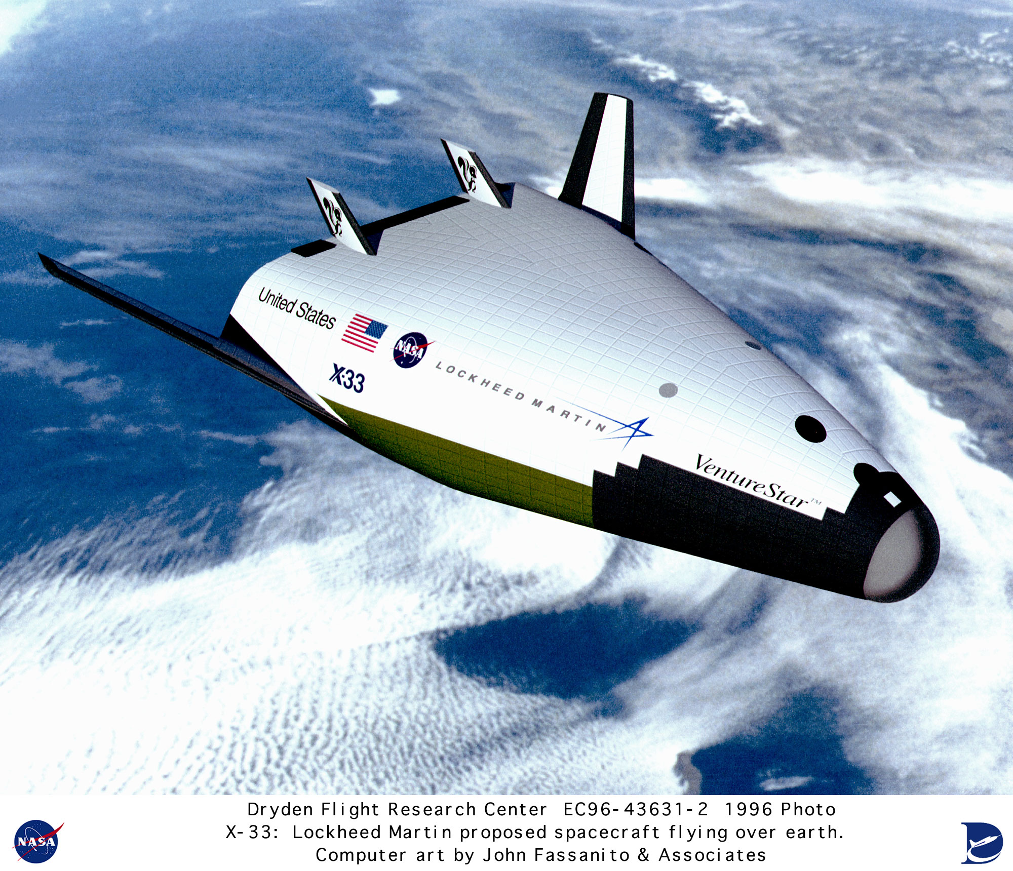


 But in the later incarnations, it looked like this:
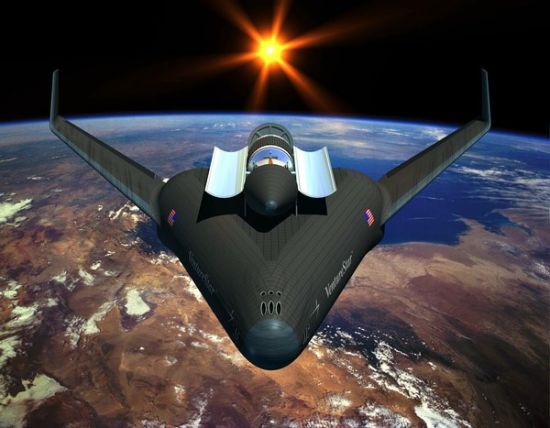

 The added wing size was to move the CP rearward to keep the CG ahead of it. 

 Partitioned propellant tanks are nothing new actually in aerospace. They are quite commonly used on jet airliners to deal with the problem of CG shift as fuel is burned off:

Concorde.
Balancing by Fuel-Pumping.
The Concorde Tank-Schematic:
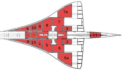
"1 + 2 + 3 + 4 are the Collector-Tanks, feeding the engines directly. Usually they feed there counterpart engines – but they can be cross-switched to feed more and/or other engines at the same time.
5 + 7 and 8 + 6 are the Main-Transfer Tanks, feeding the 4 Collector-Tanks. Initially 5 + 7 are active. If those are empty 6 + 8 take over (or must be activated from the Engineering Panel!).
5a + 7a are Auxiliary-Tanks (to 5 and 7).
9 + 10 are the Trim-Tanks for balancing forward
11 is the Trim-Tank for balancing afterward"

 Then the partitioned tanks could solve two problems of the dry mass of the X-33/VentureStar: weight growth in the tanks and in the wings.


 Bob Clark

Sunday, January 17, 2016

Altitude compensation attachments for standard rocket engines, and applications, Page 2: impulse pressurization methods.

Copyright 2016 Robert Clark

Usefulness of Altitude Compensation for All Rockets.
 I have argued altitude compensation has importance not just for SSTO's but for all launchers. For SSTO's it can double the payload possible. This leads to the unexpected conclusion that for both expendable and reusable rockets SSTO's with altitude compensation can be more cost efficient than two-stage rockets:

The Coming SSTO's: Falcon 9 v1.1 first stage as SSTO, Page 2.

 But in that blog post, it is also shown that even for two-stage rockets such as the Falcon 9 altitude compensation can improve the payload 25%.

 Another important application of it is that it makes it possible for low cost pressure-fed rockets, using multiple cores, to be able to do orbital launches. This brings orbital rockets within the range of even university aerospace departments and amateur rocket developers. Or as I like to say it:

Orbital rockets are now easy.

  Also multi-cored rockets such as the Delta IV Heavy and Falcon Heavy can double their payload by using cross-feed fueling in conjunction with altitude compensation:

Altitude Compensation Improves Payload for All Launchers.

 This is important because by doubling the Falcon Heavy payload to ca. 100 metric tons, this brings it in the range to do a manned lunar landing mission with a single launch. Also key is that it brings it close to the $1,000/kg price range space advocates have argued is necessary to allow high launch rates and additional cost reductions by volume.

 For these reasons it is important to investigate altitude compensation techniques whether or not you believe in the value of SSTO's. Ironically, though once these techniques are applied to existing rockets, it will become apparent how valuable SSTO's are.

 Altitude Compensation by "Impulse Pressure".
  There are numerous low cost methods to achieve altitude compensation with existing engines:

Altitude compensation attachments for standard rocket engines, and applications.

 In fact part of the point I'm making is the number of ways of accomplishing it at low cost. I'll describe two others here.

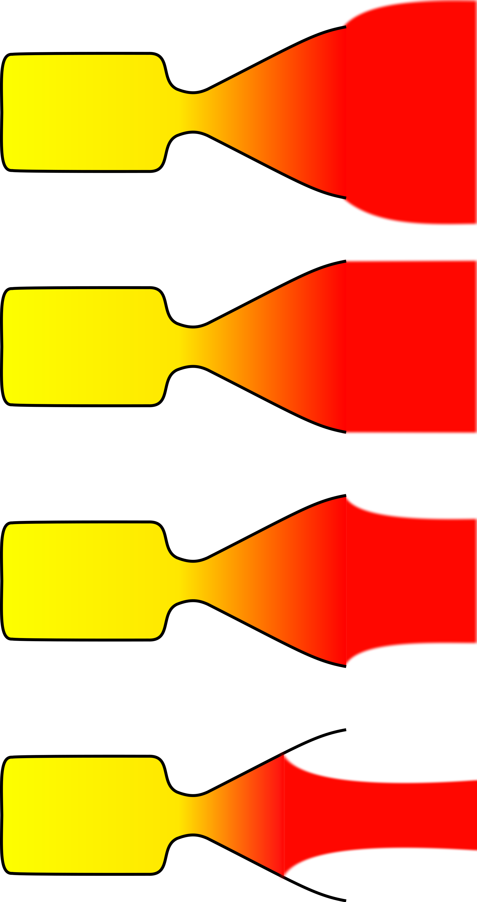
 The term "impulse pressure" or "impulse pressurization" is hardly standard. What I mean to say by it is illuminated by this image showing nozzles not optimized to altitude:


Nozzles can be (top to bottom):
underexpanded,
ambient,
overexpanded,
grossly overexpanded.
If a nozzle is under- or overexpanded, then loss of efficiency occurs relative to an ideal nozzle. Grossly overexpanded nozzles have improved efficiency relative to an overexpanded nozzle (though are still less efficient than a nozzle with the ideal expansion ratio), however the exhaust jet is unstable.[7]


  Rocket engines achieve their best efficiency at vacuum conditions with a large nozzle that allows the exhaust to expand out to near vacuum ambient pressure. However, having a large nozzle at sea level can cause unstable flow that can even tear apart an engine. It's referred to as "flow separation" and is illustrated in the bottom image. 

 Then the idea behind the "impulse pressurization" is to use a large nozzle at sea level but direct a portion of the exhaust flow out towards the sides of the nozzle to counteract this flow separation. That is, use the momentum, the impulse, of the flow to provide outwards pressure against the walls.

 There are two ways this outwards impulse can be provided: you could have the exhaust be swirled by vanes within the nozzle to cause an outwards momentum to the flow or you could have the exhaust be deflected outwards by a shelf within the nozzle that is at an angle to direct the portion of the exhaust near the walls, outwards to impinge against the nozzle walls.
  
 Note that for both of these methods you don't want most of the flow to be swirled or directed outwards but only the portion of the flow near the walls. Note also the swirl vanes or deflecting shelf can be rather far down towards the bottom of the nozzle since the degree of flow separation usually is far down towards the bottom of the nozzle. So for both of these methods most of the thrust attained at vacuum will be maintained at sea level.

 Additionally,  as the rocket increases in altitude the ambient pressure decreases and there is reduced need for this outward pressure. So the portion of the exhaust that is directed outwards will be reduced as the rocket gains altitude, to the point that the full exhaust will be allowed to flow directly downwards when the rocket reaches near vacuum. This can be done in either method by changing the angle of the swirl vanes or deflecting shelf to gradually decrease to null as the rocket achieves altitude.
(Patent pending.) 

An Earlier Patent?
 I have found one patent that attempts altitude compensation by a swirling exhaust flow, but not the deflecting shelf method:

                3,443,384
  SWIRLING FLOW NOZZLE.
James _E. Webb, Administrator of the National Aero
nautlcs and Space Administration with respect to an
invention by Frank X. McKevitt, Palos Verdes Penin
sula, Calif.
Filed May 17, 1967, Ser. No. 640,787
Int. Cl. F02k 1/02, 9/00; B05b 3/00
U.S. Cl. 60--263 4 Claims
ABSTRACT OF THE DISCLOSURE
This disclosure relates generally to rocket engines. It
teaches a method and construction for increasing the effi
ciency of a rocket engine by matching its exhaust gas
pressure with changing ambient pressure. Essentially, a
gas is introduced tangential‘ly into the engine so as to form
a vortex within the nozzle. The size of the vortex can be
used to vary the effective throat area of the nozzle. The
size of the vortex can be changed by varying the relative
amounts of axial and/or tangential flow of gases to the
nozzle.

 There are some differences. This attempts to swirl the combustion gases right within the combustion chamber and thus induce a swirl within the entire exhaust flow inside the nozzle. In contrast, my method will attempt to maintain a large proportion of the vacuum thrust and Isp by only inducing the swirl near the bottom of the nozzle and only for the outer portions of the exhaust flow.

 But a key distinction is that my proposal could be attached to the nozzle of existing engines. That is important to maintaining the idea that altitude compensation is simple and low cost to accomplish.

 Orbital Technologies Corp (ORBITEC) is investigating swirling, vortex motion within the combustion chamber of their engines:

ORBITEC Expands Vortex Rocket Engine Family with Successful Demonstration of New Propellants.
MADISON, Wis. (Nov.  10, 2015) - Sierra Nevada Corporation’s (SNC) wholly-owned subsidiary Orbital Technologies Corporation (ORBITEC) recently completed successful testing and demonstration of three different propellant combinations for its existing 30,000-pound thrust vortex rocket engine. Completing this advancement in less than a year, ORBITEC is rapidly progressing its offering of engines for orbital maneuvering, upper-stage engines that ignite at high altitude, and small-to-medium-scale air and ground launch stage engines.
http://www.sncspace.com/AboutUs/NewsDetails/2243

  Their purpose however is for cooling techniques on the combustion chamber walls not altitude compensation. However, since it uses the same method as the prior patent it may work for altitude compensation as well.


  Bob Clark


UPDATE, January 18, 2016:
  I used the term "impulse pressurization" to describe the pressure provided by a portion of the exhaust flow directed to impinge on the nozzle walls.
 Actually, there is a term in common use for this concept, called "dynamic pressure". For instance during rocket launch, rockets have to be throttled down during the period called "Max Q" where the sum of the ambient pressure at altitude and the force pressure due to the air flow at high speed is at a maximum.

 So I could have called this idea "dynamic pressurization".

Monday, January 11, 2016

Altitude Compensation Improves Payload for All Launchers.

Copyright 2016 Robert Clark

 It is unfortunate that SSTO's have been, incorrectly, deemed unviable. Since altitude compensation has only been thought of in terms of improving the payload of SSTO's, little research has gone into these methods, as SSTO's were not considered worthwhile.

  However, in point of fact altitude compensation improves the payload even for multistage rockets. In the blog post "The Coming SSTO's: Falcon 9 v1.1 first stage as SSTO, Page 2", I showed using the payload estimator by Dr. John Schilling altitude compensation improved the payload of the two-stage Falcon 9 by 25%. 

 Interestingly, the increase for the case of a rocket with side boosters can be as high as 40%. This is the case for the Delta IV Heavy. 

 According to this page the payload to LEO of the Delta IV Heavy is 25,980 kg:

Delta IV Heavy – RS-68A Upgrade.

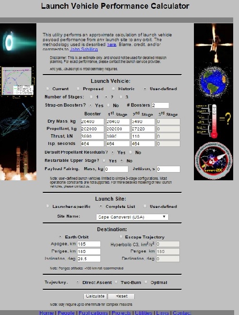
 Using the specifications from this page and inputting the vacuum values for the thrust and Isp, since the Schilling calculator requires inputting the vacuum values as it takes into account the diminution at sea level, the calculator appears as:


 And the results are:

Mission Performance:
Launch Vehicle:  User-Defined Launch Vehicle
Launch Site:  Cape Canaveral / KSC
Destination Orbit:  185 x 185 km, 28 deg
Estimated Payload:  23979 kg
95% Confidence Interval:  19412 - 29682 kg

"Payload" refers to complete payload system weight, including any necessary payload attachment fittings or multiple payload adapters

This is an estimate based on the best publicly-available engineering and performance data, and should not be used for detailed mission planning. Operational constraints may reduce performance or preclude this mission.


 A rather close approximation to the actual payload. 

 Now we'll consider the result when altitude compensating nozzles are used. First, note that there are numerous low cost methods of accomplishing altitude compensation. For instance the RL-10 engine increases its vacuum Isp to ca. 464 s simply by attaching a nozzle extension. Other low cost methods are discussed in "Altitude compensation attachments for standard rocket engines, and applications."

  Increasing the vacuum Isp to 464 s increases the thrust proportionally to (464/414)*3560 = 3,990 N. Then the inputs to the calculator now appear as:


 This gives the result:

Mission Performance:
Launch Vehicle:  User-Defined Launch Vehicle
Launch Site:  Cape Canaveral / KSC
Destination Orbit:  185 x 185 km, 28 deg
Estimated Payload:  33410 kg
95% Confidence Interval:  27137 - 41212 kg

"Payload" refers to complete payload system weight, including any necessary payload attachment fittings or multiple payload adapters

This is an estimate based on the best publicly-available engineering and performance data, and should not be used for detailed mission planning. Operational constraints may reduce performance or preclude this mission.


 About 40% higher than the case without altitude compensation. The reason why it should be expected the increase is higher than in the standard two-stage case is the center core stage in a triple-core launcher spends more of the time at high altitude where the vacuum Isp would obtain.

Altitude Compensation plus Cross-feed Fueling.
 This effect should be even more pronounced with cross-feed fueling. Cross-feed means the center core stage would have its full propellant load after the side boosters are jettisoned so it spends even more time at vacuum conditions.

 The Schilling calculator emulates cross-feed by inputting 2/3rds of the actual propellant load in the field for the side boosters, but increases the value input for the center core propellant to (1 +2/3) times the actual value (See discussion here for an explanation of how the calculator emulates cross-feed.)


 The results are:

Mission Performance:
Launch Vehicle:  User-Defined Launch Vehicle
Launch Site:  Cape Canaveral / KSC
Destination Orbit:  185 x 185 km, 28 deg
Estimated Payload:  48961 kg
95% Confidence Interval:  41112 - 58206 kg

"Payload" refers to complete payload system weight, including any necessary payload attachment fittings or multiple payload adapters

This is an estimate based on the best publicly-available engineering and performance data, and should not be used for detailed mission planning. Operational constraints may reduce performance or preclude this mission.


This is double the initial payload capability without cross-feed and altitude compensation. Note also Cross-feed fueling is not an unknown technology having been used on jet aircraft such as the Concorde for decades and also on the Space Shuttle's OMS engines.

And For the Falcon Heavy? 
 This payload for the upgraded Delta IV Heavy would rival the announced 53 metric tons(mT) LEO payload of the Falcon Heavy with cross-feed fueling and exceed that of the FH without it. But the increase in thrust of the Merlin 1D and increase of propellant load should increase the LEO payload of the Falcon 9 and Falcon Heavy. If the payload to geostationary for the F9 is increased by 30% as announced by SpaceX, then we expect the payload to LEO for the F9 and Falcon Heavy also to be increased a similar amount.  

 Then the current upgraded Falcon Heavy with cross-feed may now be in the 70 mT range. And if altitude compensation also gives this triple-cored launcher a 40% increase in payload that would bring it to the 100 mT range. This is important because this is the range estimated to be required for a manned lunar lander mission by a single launcher, and would be one in a cost range of only $120 million.

  Bob Clark

Tuesday, January 5, 2016

Triple Cored New Shepard as an orbital vehicle.

Copyright 2016 Robert Clark


 Blue Origin made a significant achievement in successfully landing their New Shepard rocket after a suborbital spaceflight:


 As their next development Blue Origin intends to make a several million pound thrust rocket capable of sending 25 metric tons to LEO. This would be a very large and expensive development for their first orbital rocket, comparable in size to the largest orbital rockets available now, larger for example than the Falcon 9.

 I suggest an intermediate development for their first orbital rocket. Running the numbers, their New Shepard suborbital rocket could be used to make an orbital rocket using three cores with a smaller upper stage, a la the Delta IV Heavy.

 It would have a payload to LEO in the range of 3,000 kg, about the size of the Arianespace Vega rocket. The Vega costs in the range of $35 million. Considering the small size of the New Shepard, even at three cores, Blue Origin should be able to beat this price.

 Moreover, this version would have the capability to be reusable. SpaceX is planning to make the three cores of the Falcon Heavy reusable by returning the two side cores to the launch site and recovering the central core by a barge landing out at sea. Quite likely this would work for a 3-cored New Shepard launcher as well.

Specifications of the New Shepard BE-3 engine.


 Here's a formula for calculating the sea level thrust from the vacuum thrust and back pressure:


F = q × Ve + (Pe - Pa) × Ae
where F = Thrust
q = Propellant mass flow rate
Ve = Velocity of exhaust gases
Pe = Pressure at nozzle exit
Pa = Ambient pressure
Ae = Area of nozzle exit
http://www.braeunig.us/space/sup1.htm

 Estimating the nozzle exit diameter as 1 meter, the exit plane area would be: π*0.5^2 = .7854. Then the back pressure to be subtracted off would be 101,000Pa*.7854 = 79,325 N. 
Blue Origin has given the sea level thrust as 110,000 lb, 110,000*4.45 = 489,500 N. So the vacuum thrust is 489,500N + 79,325N = 568,825 N. 

 We also need to calculate the Isp. One other piece of information will allow us to calculate this. This Blue Origin page gives the horsepower of the BE-3 as over 1,000,000 hp:

https://www.blueorigin.com/technology

 The power of a jet or rocket engine is (1/2)*(thrust)*(exhaust velocity). The 1,000,000 hp at sea level is 1,000,000*746 = 746,000,000 watts. Then using the formula the exhaust velocity at sea level is 3,048 m/s, and the Isp is 310 s.

 Since (thrust) = (exhaust velocity)*(propellant flow rate), we also get the propellant flow rate as 489,500/3,048 = 160.6 kg/s. Now we can get the exhaust velocity and Isp at vacuum. From the 568,825 N vacuum thrust, we get the vacuum exhaust velocity as 568,825 N/160.6 = 3,540 m/s, and the vacuum Isp as 360 s.


  It is interesting that the diameter and sea level and vacuum Isp's are close to those of the RL-10A5,  the sea level version of the RL-10 used on the DC-X:

http://www.astronautix.com/engines/rl10a5.htm


Size Specifications for the New Shepard.
 The Blue Origin environmental impact statement:

Final Supplemental Environmental Assessment for the Blue Origin West Texas Launch Site.
February 2014
https://www.faa.gov/about/office_org/headquarters_offices/ast/media/Blue_Origin_Supplemental_EA_and_FONSI.pdf

on p. 4 lists the max dry mass as 30,000 pounds (13,600 kg) and max propellant load as 60,000 pounds (27,300 kg). This corresponds to estimates made of the New Shepard gross mass based on its dimensions.


 We need also a small upper stage. The cryogenic upper stage of the Ariane 4 will suit the purpose, the Ariane H10-3. It had a dry mass of 1,240 kg and a propellant mass of 11,860 kg. The Isp was 445 s with a vacuum thrust of 64.8 kN. However, simply using a nozzle extension as on the RL-10B-2 can give it likewise an Isp of 462 s and vacuum thrust of 110 kN. So we'll use these values.

 Use now Dr. John Schilling's Launch Performance Calculator to estimate the payload. We'll also use cross-feed fueling to increase the payload. Cross-feed fueling is not an unknown technology having been used on jet aircraft such as the Concorde for decades and also on the Space Shuttle's OMS engines.


 To emulate cross-feed fueling with the Schilling calculator for two side boosters, enter in 2/3rds of the actual propellant load into the propellant field for the side boosters. And for the central core enter in (1 + 2/3) times the propellant load in the field for the first stage. (See  discussion here for explanation of how the Schilling calculator emulates cross-feed fueling.)


 So in the dry mass fields for the side boosters and first stage enter 13,600 kg. And in the propellant field for the side boosters enter 18,200 kg and 45,500 kg for the first stage. For the second stage enter 11,860 kg for the propellant and 1,240 kg for the dry mass.


 In the thrust fields and Isp fields enter in the vacuum values. So for the side boosters and first stage enter 568.8 for the thrust in kilonewtons and 110 for the second stage. In the Isp fields enter 360 for the side boosters and first stage Isp in seconds and 462 for the second stage. 


 For the "Restartable upper stage" option check "No", otherwise the payload will be reduced. Select Cape Canaveral as the launch site and enter 28.5 for the launch inclination in degrees to match the latitude of the launch site.


 The calculator gives:


Mission Performance:
Launch Vehicle:  User-Defined Launch Vehicle
Launch Site:  Cape Canaveral / KSC
Destination Orbit:  185 x 185 km, 28 deg
Estimated Payload:  3420 kg
95% Confidence Interval:  2766 - 4205 kg

"Payload" refers to complete payload system weight, including any necessary payload attachment fittings or multiple payload adapters

This is an estimate based on the best publicly-available engineering and performance data, and should not be used for detailed mission planning. Operational constraints may reduce performance or preclude this mission.


  This would be using an Arianespace upper stage. But this would be a competitor to their Vega launcher so that is problematical. Blue Origin could use instead the Rl-10B2 engine and their own constructed upper stage. The RL-10 though is a rather expensive engine. Another possibility is the 25,000 lb thrust hydrolox engine being developed by XCOR.


Altitude Compensation Increases Payload Even for Multistage Vehicles.

 It is unfortunate that SSTO's have (incorrectly) been deemed unviable. Since altitude compensation has only been thought of in terms of improving the payload of SSTO's, little research has gone into such methods, with SSTO's not being considered worthwhile.

 However, in point of fact altitude compensation improves the payload even for multistage rockets. As with the RL-10B-2 we can get a vacuum Isp of 462 s on the New Shepard hydrolox engine simply by the addition of a nozzle extension. Other methods of accomplishing it are discussed in the blog post "Altitude compensation attachments for standard rocket engines, and applications."


 Increasing the Isp will also increase the thrust proportionally. So at a 462 s Isp for the BE-3, the thrust becomes 568.8*(462/360) = 730 kN. Entering these values into the thrust and Isp fields for the side boosters and first stage gives the result:


Mission Performance:
Launch Vehicle:  User-Defined Launch Vehicle
Launch Site:  Cape Canaveral / KSC
Destination Orbit:  185 x 185 km, 28 deg
Estimated Payload:  5302 kg
95% Confidence Interval:  4359 - 6438 kg

"Payload" refers to complete payload system weight, including any necessary payload attachment fittings or multiple payload adapters

This is an estimate based on the best publicly-available engineering and performance data, and should not be used for detailed mission planning. Operational constraints may reduce performance or preclude this mission.


 This now is a serious payload capability. Note for example NASA awarded Orbital Sciences with a billion dollar contract to deliver payload to the ISS with their Antares rocket with a 5,000 kg payload to LEO capacity.


 Bob Clark


UPDATE, February, 3, 2016:

 Jonathan Goff on his SelenianBoondocks.com blog raised the possibility that a single New Shepard could serve as a booster for an orbital rocket. I confirmed it could at the 1 to 2 metric ton payload range by using the same type of hydrolox upper stage as discussed above in the triple-cored case:

New Shepard as a booster for an orbital launcher.
http://exoscientist.blogspot.com/2016/01/new-shepard-as-booster-for-orbital.html

 It could also serve as a booster for a smaller launcher by using instead one of the Star solid rocket upper stages, giving a few hundred kilos payload. This would have the advantage that little extra development would be required.

 Plus, it may allow Blue Origin to beat SpaceX at reusing a booster for an orbital launcher.

Tuesday, September 23, 2014

A SpaceX Heavy Lift Methane Rocket, Page 2.

Copyright 2014 Robert Clark

 In the blog post A SpaceX Heavy Lift Methane Rocket I discussed some possibilities for a heavy lift rocket using SpaceX's planned methane engine, the Raptor. Those calculations were based on the initial released values for its thrust of 660,000 lbs, 300,000 kilograms-force. However, recently SpaceX has said the Raptor may have a thrust of 1,800,000 lbs in vacuum, 1,600,000 lbs at sea level. So I'll give some revised estimates for its payload. 

 As before I suggest using the same tooling for the core stage as that used for the SLS core to save on development costs. Corresponding to the new higher thrust of the Raptor I'll use the full tank size of the SLS core, which would hold 1,000 metric tons (MT) of hydrogen-lox propellant. Since methane-lox is 2.4 times as dense as hydrogen-lox, the SpaceX methane-lox core will hold 2,400 mT of propellant. The relative densities of methane-lox compared to hydrogen-lox are given in Table 1 of this report:

Alternate Propellants for SSTO Launchers.
Dr. Bruce Dunn
Adapted from a Presentation at:
Space Access 96
Phoenix Arizona
April 25 - 27, 1996

 In regards to the specifications of the methane rocket engine it should be noted the high vacuum Isp of 380 s  cited really would only be expected of a vacuum optimized nozzle. Such engines can not be operated at sea level. However, in an upcoming blog post I'll discuss some altitude compensation methods that will allow the engine to have this vacuum optimized Isp while still being able to operate at sea level. So I'll assume both the first stage and upper stage engines have the vacuum Isp of 380 s.

 As before I'll take the number of engines for the core as five and the propellant-to-dry mass ratio as 20 to 1. For the upper stage I'll take the propellant size as approx. 1/5th that of the core stage, at 500,000 kg with the same mass ratio, and use a single Raptor for the upper stage.

SSTO Case.
 We'll use again Dr. John Schilling's Launch Vehicle Performance Calculator. Input the thrust as the value of the vacuum thrust in kilonewtons of 5 Raptors as 5*8200 kN = 41,000 kN, and the Isp as the vacuum Isp of 380 s. Input the propellant mass as 2,400,000 kg and the dry mass as 1/20th of this at 120,000 kg. For the "Default Propellant Residuals?" option select "Yes", and for the "Restartable Upper Stage?" option select "No". Selecting "Yes" for this last option would reduce the calculated payload.

 Use the default altitude of 185 km. Select Cape Canaveral as the launch site with an orbital inclination of 28.5 degrees to match the latitude of the launch site. Then the Calculator gives the result:

Mission Performance:
Launch Vehicle:  User-Defined Launch Vehicle
Launch Site:  Cape Canaveral / KSC
Destination Orbit:  185 x 185 km, 28 deg
Estimated Payload:  110395 kg
95% Confidence Interval:  75079 - 152433 kg

 So this larger version could give 110,000 kg payload as an SSTO.

Two Stage Case
For the two stage case, in the column for the 2nd stage, input the propellant mass as 500,000 kg and the dry mass as 25,000 kg. Input the thrust as the vacuum thrust of 8,200 kN, and the Isp as the vacuum Isp of 380 s. Then the calculator gives the result:

Mission Performance:
Launch Vehicle:  User-Defined Launch Vehicle
Launch Site:  Cape Canaveral / KSC
Destination Orbit:  185 x 185 km, 28 deg
Estimated Payload:  196089 kg
95% Confidence Interval:  162727 - 236334 kg

  Close to 200 metric tons payload to LEO. Actually since the mass ratio of stages improve as you scale them up, quite likely the mass ratio will be better than just ca. 20 to 1, perhaps in the range of 25 to 30 to 1. This would then improve our payload to above 200 metric tons.

Cross-Feed Fueling for Multiple Cores.
 We'll just look at the 3 core case here. As described in the A SpaceX Heavy Lift Methane Rocket post, we emulate cross-feed fueling in the Schilling calculator by inputting for the two side boosters 2/3rds the actual  propellant mass, and also increase the first stage propellant mass by an additional 2/3rds. The rest of the specifications, dry mass, thrust, Isp remain the same. 

 So enter 2 as the number of side boosters. Then in the column for the boosters, input 1,600,000 kg for the propellant mass and 120,000 kg for the dry mass of the boosters. Enter the actual vacuum thrust of 41,000 kN and Isp as 380 s. Then the calculator gives the result:

Mission Performance:
Launch Vehicle:  User-Defined Launch Vehicle
Launch Site:  Cape Canaveral / KSC
Destination Orbit:  185 x 185 km, 28 deg
Estimated Payload:  536113 kg
95% Confidence Interval:  449806 - 639526 kg
 Over 500 metric tons of payload! This rocket however would be truly massive at 3 times the mass of the Saturn V. This would likely require a new,expensive launch pad to handle a rocket this size.


  Bob Clark

UPDATE, October 25, 2014:

 Some methods of accomplishing the altitude compensation mentioned are discussed here:

Altitude compensation attachments for standard rocket engines, and applications.
http://exoscientist.blogspot.com/2014/10/altitude-compensation-attachments-for.html

Thursday, October 31, 2013

A SpaceX Heavy Lift Methane Rocket.

Copyright 2013 Robert Clark

 SpaceX has announced development of a new 300 metric ton (mT), 660,000 lb, thrust engine, the Raptor:

SpaceX Could Begin Testing Methane-fueled Engine at Stennis Next Year.
By Dan Leone | Oct. 25, 2013

 This is supposed to be used for a proposed heavy lift rocket to be used for manned Mars missions. However, I'm not a fan of the 9 engine arrangement used on the Falcon 9, and even less so of the 27 engines proposed for the Falcon Heavy. I would hope that SpaceX would transition to the larger engines for these rockets as well.

 We can do an estimate of the size and payload capacity of the methane-fueled heavy lift rocket. Previous statements from SpaceX have suggested the core of the rocket might be 7 meters wide. However, I wanted to use an 8 meter wide core to make use of the tooling used for the shuttle external tank to save on costs. If we used the same size tank as the shuttle ET then we can calculate the mass of propellant could be carried as methane-lox instead of hydrogen-lox by comparing their densities.

SSTO Case.

 This report by Dr. Bruce Dunn gives densities and performance data on several propellant combinations:

Alternate Propellants for SSTO Launchers.
Dr. Bruce Dunn
Adapted from a Presentation at:
Space Access 96
Phoenix Arizona
April 25 - 27, 1996
https://web.archive.org/web/20140215015634/http://www.dunnspace.com/alternate_ssto_propellants.htm

 In Table 1 the density of methane-lox is 828 kg/m^3 and for hydrogen-lox, 358 kg/m^3. So the same volume would hold 2.4 times more methane-lox. This would put it in the range of 1,700 mT for the methane-lox. Actually it would probably be a little more than this because likely SpaceX would use common bulkhead design for the tank which would mean it could hold more propellant.

 There have been some estimates proposed for this launcher that use 7 copies of Raptor engine on the core. This many probably would be needed when you take into account the reduction in thrust at sea level if using a 1,700 mT sized tank. However, I wanted to keep the maximum number of engines on a core to be at most what was used on the Saturn V at 5 engines. Therefore I'll reduce the propellant load to 1,000 mT.

 For the dry mass, note that Elon has said that the Falcon 9 v1.1 first stage has a propellant fraction in the range of 96%, for a mass ratio of 25 to 1. As you can see in Dunn's Table 1 the density of methane-lox is about 80% that of kerosene-lox. So I'll estimate the mass ratio for the core as 20 to 1. This will put the dry mass of the core at 52,630 kg, which I'll round off to 50,000 kg.

 The vacuum thrust in kilonewtons for 5 Raptors will be 5*300*9.81 = 14,715 kN. We'll calculate the payload for this core stage first as an SSTO. Input these numbers into Dr. John Schillings Launch Performance Calculator. Select "No" for the "Restartable Upper Stage" option, otherwise the payload will be reduced. Use the default altitude of 185 km. Select Cape Canaveral as the launch site with an orbital inclination of  28.5 degrees to match the latitude of the launch site. Then the Calculator gives the result:

Mission Performance:
Launch Vehicle:  User-Defined Launch Vehicle
Launch Site:  Cape Canaveral / KSC
Destination Orbit:  185 x 185 km, 28 deg
Estimated Payload:  42487 kg
95% Confidence Interval:  28319 - 59338 kg

 Two stage case.  

 For the two stage case, I'll take the the upper stage as using a single Raptor and at 1/5th the size of the first stage, so at 200 mT propellant mass and 10 mT dry mass. Enter in 2,943 kN for the thrust of a single Raptor in the column for the second stage and select "Optimal" for the trajectory. Then the Calculator gives:

Mission Performance:
Launch Vehicle:  User-Defined Launch Vehicle
Launch Site:  Cape Canaveral / KSC
Destination Orbit:  185 x 185 km, 28 deg
Estimated Payload:  77569 kg
95% Confidence Interval:  64244 - 93424 kg

  However, for this upper stage likely you won't be able to get as good a mass ratio as the first stage since it would undergo a higher acceleration as the propellant is burned off. This would require a stronger and therefore heavier structure. Then the payload would be reduced below this, though likely still above ca. 70 mT.

Cross-Feed Fueling for Multiple Cores.

 For higher payloads we'll use a combination of 2 or 3 cores. For both of these we'll use cross-feed fueling. To emulate cross-feed fueling with the Schilling Calculator, note that during the parallel burn portion of the flight the propellant for the center core engines is coming from the side booster stage(s). This ensures that the center core will have a full propellant load during its solo burn portion of the flight, after the side booster(s) are jettisoned. 

 So the total amount of propellant burned during the parallel burn portion, is that of the side booster(s) only. But the Schilling Calculator assumes the amount of propellant burned in the center core during the parallel burn is the same as the amount burned in each side booster. So enter in the Calculator for the booster propellant load a fraction of the actual propellant load of a core equal to the number of side boosters divided by the number of cores. So if you're using 2 cores with one used as a side booster enter in the Calculator booster column 1/2 the amount of the actual core propellant load. And if using 3 cores with 2 used as side boosters, enter in 2/3rds the actual core propellant load in the booster section. This will ensure the Calculator interprets the total propellant burned during the parallel burn portion is that of the actual side booster(s) only.

 But you also want the Calculator to take the amount of propellant burned during the center core's solo burn portion of the flight as that of a full propellant load. Since it is already taking it to have burned the same amount as what the side boosters have burned during the parallel burn portion, add this amount onto the actual propellant load of a core and enter this into a first stage column of the Calculator. For the other specifications for both booster(s) and center core such as Isp, dry mass, and thrust enter in the actual values.

2 Core Version.
 Here one core will be used as a side booster. As described above, to emulate cross-feed fueling enter in the Calculator only 500,000 for the propellant load of the booster. Enter in though the actual dry mass of 50,000 kg, actual thrust of 14,715 kN, and actual Isp of 380 s. And for the center core, enter in the first stage column for the propellant 1,500,000 kg, but the real dry mass, thrust, and Isp values. Also use all the actual values for the second stage. Then the Calculator gives the result:

Mission Performance:
Launch Vehicle:  User-Defined Launch Vehicle
Launch Site:  Cape Canaveral / KSC
Destination Orbit:  185 x 185 km, 28 deg
Estimated Payload:  145339 kg
95% Confidence Interval:  121566 - 173707 kg
 This is surprisingly high. However, another consideration besides the fact that the second stage mass ratio likely won't be as good as used here, is that as propellant is burned off during the parallel burn portion, the engines will have to be gimbaled because the propellant is only coming from the side booster stage. This will reduce the payload somewhat.

3 Core Version.
 Here two cores will be used as side boosters. As discussed, to emulate cross-feed we'll enter in the booster column for the propellant load, 2/3rds the actual amount, so only 660,000 kg. And for the center core's propellant load, enter into the first stage column 1,660,000 kg. All the other specifications are given their actual values. Then the Calculator gives:

Mission Performance:
Launch Vehicle:  User-Defined Launch Vehicle
Launch Site:  Cape Canaveral / KSC
Destination Orbit:  185 x 185 km, 28 deg
Estimated Payload:  211268 kg
95% Confidence Interval:  177052 - 251940 kg

  Remarkably high. Twice the payload of the SLS at about the same gross mass.

   Bob Clark

UPDATE, May 1, 2015:

 To get such high performance you would need the lower stage engines to have the high vacuum Isp of 380 s. But lower stage engines usually compromise their performance to use a single nozzle that can work both at low altitudes and high altitudes. Ideal then would be a nozzle that could adapt to the altitude, an altitude compensating engine.
 Some possibilities for this are discussed here:

Altitude compensation attachments for standard rocket engines, and applications.
http://exoscientist.blogspot.com/2014/10/altitude-compensation-attachments-for.html

Could Blue Origin develop a lander for Artemis III?

Copyright 2025 Robert Clark SpaceX is coming under increasing criticism for its delay in developing the Starship lunar lander: U.S. Is Losin...