Monday, July 30, 2018

Beamed propulsion doable now, and with it space solar power, Page 2: carbon nanotube beam production.

Copyright 2018 Robert Clark
(patents pending)

 In the blog post, Beamed propulsion doable now, and with it space solar power, I discussed microLED's whose extremely high light output can be used for orbital beamed propulsion, space solar power, or laser missile defense. I wondered though if their output could be made even larger by making the light emitters at the nanoscale rather than the microscale.

 Of course for anything at the nanoscale the first thing to comes to mind are the carbon nanotubes because they have so many extraordinary properties. We'll discuss some possible ways to generate the high intensity light via carbon nanotubes. Some of them may also work with nanowires of other types. For each, we'll follow the example of the microLED's of using nanoscale parabolic mirrors to collimate the light thereby forming a more intense beam.

Glow Discharge Light.
One way nanotubes can create light is though electrical breakdown producing an ionization plasma. In general, high voltage passed througn thin wires or though a sharp point electrode can generate a plasma, known as a corona discharge:

Corona discharge.
When the potential gradient (electric field) is large enough at a point in the fluid, the fluid at that point ionizes and it becomes conductive. If a charged object has a sharp point, the electric field strength around that point will be much higher than elsewhere. Air near the electrode can become ionized (partially conductive), while regions more distant do not. When the air near the point becomes conductive, it has the effect of increasing the apparent size of the conductor. Since the new conductive region is less sharp, the ionization may not extend past this local region. Outside this region of ionization and conductivity, the charged particles slowly find their way to an oppositely charged object and are neutralized.

 Or electric arc discharge:

Electric arc.
An electric arc between two nails
An electric arc, or arc discharge, is an electrical breakdown of a gas that produces an ongoing electrical discharge. The current through a normally nonconductive medium such as air produces a plasma; the plasma may produce visible light. An arc discharge is characterized by a lower voltage than a glow discharge and relies on thermionic emission of electrons from the electrodes supporting the arc. An archaic term is voltaic arc, as used in the phrase "voltaic arc lamp".

 The thinner the wires or sharper the point electrodes the more intense the electrical field and the more intense will be the light generated in accordance with Paschen's Law. Because the nanotubes are so thin but at the same time can carry high electrical power, intense plasma generated light can be produced.

Fluorescent Light.
 Fluorescent lamps work by sending an electric current through mercury vapor. This induces UV light to be emitted. The UV interacts with a phosphor on the inner surface of the lamp to emit visible light. The fluorescent lamps could be made at the nanoscale using nanotubes or nanowires. Note that it might even be sufficient to make a UV beam in which case a phosphor would not be needed to make a visible light beam.

Cathode Ray Tube.
 Cathode ray tubes also called vacuum tubes were the primary method of operation for TV's prior to the advent of flat-screen TV's. They work by generating an electron beam and directing it a phosphor covered screen to generated light. Carbon nanotubes are known as efficient electron emitters via application of electric current so can be used to make a CRT at the nanoscale.

Neon Lights.
 Neon lights also work by sending electric current through an inert gas such as neon or xenon. Unlike the fluorescent and CRT cases though it produces directly visible light rather than needing a phosphor.


  Bob Clark


Friday, July 20, 2018

Beamed propulsion doable now, and with it space solar power.

Copyright 2018 Robert Clark
(patents pending)

  A dream of advocates of low cost space access has been beam propulsion of various types, whether laser, microwave, or particle beams. 

This image displays how beamed microwave technology could be used to launch payloads into space. Source: Escape Dynamics


 The problem has been the size of the laser beam installation needed to launch sizable payloads has been prohibitive.

 The standard estimate for how much payload you can send to orbit with laser-propulsion is 1 kg in payload for 1 megawatt (MW) of laser power. See for example this report by the late Jordin Kare:  

Modular Laser Launch Architecture: Analysis and Beam Module Design. 
Final Report 
USRA Subcontract Agreement No. 07605-003-015 
30 April 2004 Revised 18 May 2004 
Dr. Jordin T. Kare 
Kare Technical Consulting 
908 15th Ave. East jtkare@****.*** 
Seattle, WA 98112 206-323-0795 

 By this measure to launch a 5 metric ton capsule payload would require 5 gigawatts of laser power. In a follow up post I'll discuss some methods that might decrease the amount of power required.

 A further consideration about the power requirements is that if done via some type of gas generator these are typically only about 33% efficient in conversion to electricity, so it would actually take 15 gigawatts. This would be like a nuclear power plant installation. Another possibility would be to use large chemical engines such as the SSME's to generate the heat energy which would then be converted to electrical energy. Three SSME's generated in the range of 27 gigawatts. This would suffice for in the range of a 9 metric ton payload.

 It would take about a day to refurbish the engines for another shot, and then there would only be in the range of 100 shots possible based on the reusability of the SSME's. Considering this would be the primary cost and the vehicle itself would be highly reusable this would still result in a substantial reduction in launch cost.

 Another possibility might be the nine engines of the Falcon 9. These also produce in the range of gigawatts of power. They are also intended to be reusable. But reportedly the number of reuses will only be in the few dozen range.

  As I mentioned, the primary impediment to sizable payload laser propulsion has been the costs of the large laser installation. Currently, the costs for lasers are in the range $15 per watt. Then for 5 gigawatts of laser power that would be $75 billion. That's too much development cost for a single launch installation.

 However, a key new advance may bring the “laser”, or sufficient replacement, cost within what is feasible. The key advance is in the realm of microscale LED's that have remarkably high power density per area:

InfiniLED MicroLEDs achieve 300 W/cm2 output density from tiny source.
The MicroLEDs semiconductor manufacturing process includes construction of a
parabolic reflector to enable optimal light control and high efficiency from
micro-meter-sized LEDs.
Published on:Jan 29, 2013
By Maury Wright
https://www.ledsmagazine.com/articles/2013/01/infiniled-microleds-achieve-300-w-cm-sup-2-sup-output-density-from-tiny-source.html

 The report discusses micro-scale LED's whose light output scales up to 300 W per square centimeter, 3 megawatts per square meter. So a gigawatt could be produced from an array 30 meters on a side. 

 Another article on the InfiniLED's:

Products, Materials & Tools | Jan 21, 2013
InfiniLED MicroLEDs achieve Ultra-High Light Intensity.
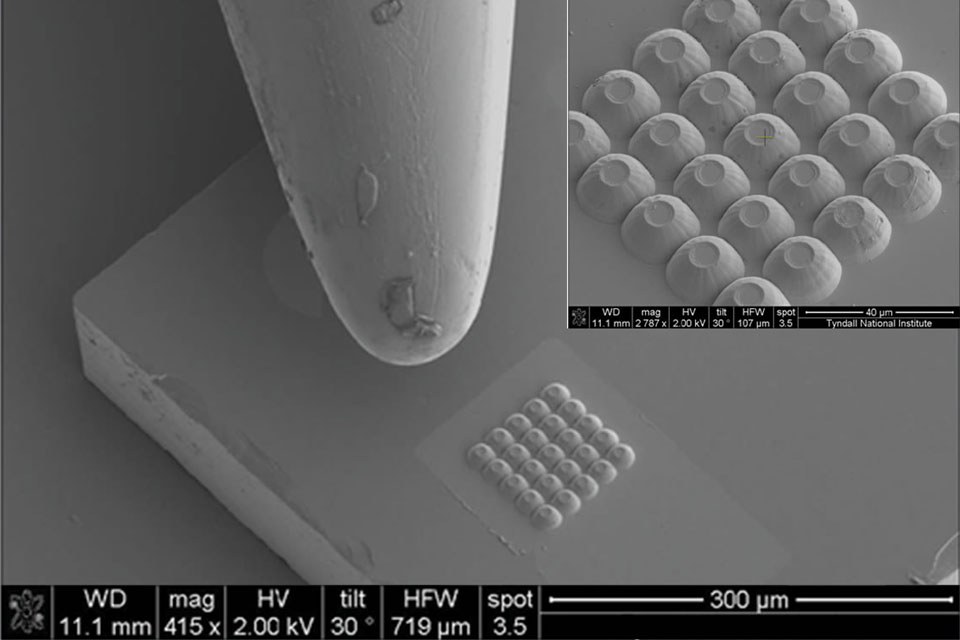
InfiniLED’s latest MicroLEDs (µLEDs) have produced record optical beam intensity. This new device is capable of producing up to 1mW of light from a single 20µm pixel at 405nm. This is equivalent to a light output density of more than 300 W/cm2 – the highest recorded for a commercially available LED type device.

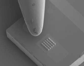
A cluster of 25 MicroLEDs beside the tip of a needle. The parabolic reflector shape can be seen in the inset close-up
https://www.led-professional.com/products/leds_led_modules/infiniled-microleds-achieve-ultra-high-light-intensity

 From the appearance of these micro-scale LED's, they should permit simple automated production to produce many copies to cover a macro-scale area to generate light even at gigawatt power levels.

  A description of the mode of operation of the microLED:

MicroLED Sources Enable Diverse Ultralow-Power Applications.
Photonics Spectra
Oct 2013
DR. WILLIAM HENRY, INFINILED

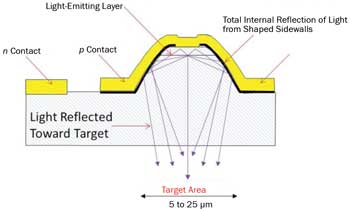
Figure 1. This microLED cross section shows total internal reflection leading to high extraction efficiency through a single surface.


Figure 2. A cluster of 25 microLEDs beside the tip of a needle.

https://www.photonics.com/Article.aspx?AID=55014

 However, for laser propulsion to be useful the beam has to be focused on the target spacecraft. This is possible for the coherent light of a laser. However, it turns out what is only really needed is for the light to be collimated, that is, consisting of parallel beams, and the light produced by these microLED arrays is collimated. From the "InfiniLED MicroLEDs achieve 300 W/cm2 output density from tiny source" article:

The MicroLED is built using an LED semiconductor structure and can be
driven like standard LEDs. But the manufacturing process, which includes
etching of a parabolic reflector at the semiconductor level, delivers a
collimated beam like a laser (see the parabolic structure in the nearby
photo). The result is both high-intensity light and high efficiency.
"This device can be seen as a cross-over between the power and collimation
of a laser and the simplicity of an LED. The unique devices enable a range
of applications," said chief commercial officer of InfiniLED, Bill Henry.
"InfiniLED are proud to have achieved the landmark performance of optical
density greater than 300 W/cm2. This was achieved without the need for
external optics indicating the potential for further improvement of the
performance."


 This means the light rays are parallel. But this is what is needed for the light to be focused to a point (Airy disk) using a parabolic mirror. It doesn't really need to be coherent like a laser. Not actually having to make it be a laser inherently makes it a simpler and cheaper system. However, we will need to array many copies of the MicroLED's to create a large beam. But when the pattern is repeated, likely the degree of collimation will be degraded somewhat over the entire size of the array. That needs to be determined. 

 Still, even if there is a lack of collimation over a large array, we can produce a large collimated beam from the individual collimated beams using an optical element called a collimator:

Collimated light.


 There is the question of whether non-coherent light will have worse disperion through the atmosphere. However, this report discusses experimentation that suggests atmospheric dispersion is actually worse for lasers than for noncoherent light generated by LED's. See for instance the video in Fig. 2 on this page:

Optical communications using coherent and non-coherent light. 
http://modulatedlight.org/optical_comms/optical_about.html

  Another possible advantage of just using LED's rather than going for a laser is that LED's can have high efficiency, as much as 80%, though the efficiency of the InfiniLED's isn't specified. Lasers on the other hand typically only have an efficiency of 30%.

  There is also the cost advantage of just using LED's instead of actual lasers. The cost for LED's is about $1 per watt. Then potentially the cost of the beam itself might only $5 billion for the 5 gigawatt installation for a 5 metric ton launcher. This is within the range for the development cost of a new orbital launcher. 

 However, the microLED's are a new development so their cost might be above the $1 per watt level. Still, Apple is expected to start soon on large scale production of microLED's for use in cell phones, tablets, and TV screens. This will tend to drive down costs.

 The large power requirements would be for launching large payloads such as manned capsules. But there is a market for small payloads. In fact, the DoD has funded programs to develop launchers for payloads in the range of 25 kg to 40 kg at a ca. $1 million launch cost. None of the funded programs have succeeded so far but this cost and size range should now be well within the capabilities of laser launch. A 25 kg payload at the 1 MW per kg measure would require 25 megawatts of laser power, or perhaps of 75 megawatts of thermal power if the electrical power required is provided by a gas turbine.

 But gas turbines at this power range are available for sale at the few tens of millions of dollars cost range:

http://nyethermodynamics.com/trader/kwprice.htm

 Since these are designed to operate continually they could provide thousands of shots. They would also satisfy the DoD requirement of "launch on demand".

Laser Defense Application.
 With Iran and North Korea possibly acquiring the capability to deliver nuclear tipped ICBM's, the need for missile defense becomes more urgent. A promising program for this wound up being cancelled:

27 Sep 2017 | 15:11 GMT
Laser Weapons Not Yet Ready for Missile Defense.
Prototype laser weapons can zap drones from the sky. But they won't protect the U.S. from North Korean nuclear missiles.
https://spectrum.ieee.org/tech-talk/aerospace/military/no-quick-laser-missile-defense

 This was a megawatt-class laser carried on a modified 747. However, to be effective it would have to have 20 to 30 times more power than that. But the InfiniLED's can manage 3 megawatts per square meter. So to get a 20 megawatt beam you would only need a 2.5 by 2.5 meter array of InfiniLED's.

 There was also a problem with the power requirements at lightweight as discussed here:

Reasons to Doubt Laser Missile Defense.
ARMS CONTROL NOW
Authored by Ryan Fedasiuk and Kingston Reif on May 14, 2018
https://www.armscontrol.org/blog/2018-05-14/reasons-doubt-laser-missile-defense

 The weight required for the power production had to be decreased almost by a factor of ten to the range of 5 kg per kilowatt. The microLED's themselves would be quite lightweight so the question remains about the power production and conversion to electricity.

 As described here we already have well above this capability for power production/conversion:

Nuclear powered VASIMR and plasma propulsion doable now.
https://exoscientist.blogspot.com/2015/08/nuclear-powered-vasimr-and-plasma.html

See for instance the listed examples here:

Power-to-weight ratio.
https://en.wikipedia.org/wiki/Power-to-weight_ratio

 Both the heat engines in converting thermal energy to mechanical energy and electric generators in converting mechanical to electrical energy are well above the required power to weight ratio.

Space Solar Power Application.
  In this blog post I suggested we have the capability for space-based solar power:

Economical Space Solar Power Now Possible.
http://exoscientist.blogspot.com/2014/04/economical-space-solar-power-now_19.html

 The reason was the huge mass thought to be needed for lofting the required solar cells can be drastically reduced by using nanotube-based mirrors as solar collectors to focus the light on much smaller solar cells. 

 Now with beamed propulsion the cost to orbit is reduced even further, in fact approaching just the energy cost to orbit with multiple launches. With orbital assembly you wouldn't need gigawatt,  multiton launch installations. You could send very many tens to hundreds of kilo mass payloads to orbit to be assembled into the solar collector arrays. With the payloads in this size range you could use gas turbines to provide the power supply to make continuous launches.

 However, a key aspect was left out of that earlier post: the transmission of the power back to Earth. But we now have the capability of making high power collimated light beams at lightweight as well.


    Bob Clark


Tuesday, July 10, 2018

DARPA's Spaceplane: an X-33 version, Page 3.

Copyright 2018 Robert Clark

 In the previous post "DARPA's Spaceplane: an X-33 version, Page 2"I discussed some recent high strength metal alloys that might give the X-33 and VentureStar even lighter weight propellant tanks than originally envisioned. Still, because of the conformal, noncylindrical shape of the tanks, they would still not have the weight efficiency of a cylindrically shaped rocket. Then I'll discuss some methods that will come close to having the weight efficiency of cylindrical tanks.

Multi-tubed Propellant Tanks.
 One possibility would be to achieve the same lightweight tanks as cylindrical ones by using multiple, small diameter, cylindrical tubes. 

 A similar idea is described here:

OCTOBER 1, 2009 | MECHANICAL & FLUID SYSTEMS
Assemblies of Conformal Tanks
Space is utilized efficiently and sloshing is reduced.
This Prototype Assembly of Conformal Tanks was built to demonstrate the feasibility of building such an assembly to fit an approximately toroidal available volume.
https://www.techbriefs.com/component/content/article/tb/techbriefs/mechanics-and-machinery/5780

 You could get the same volume by using varying lengths and diameters of the multiple cylinders to fill up the volume taken up by the tanks. The cylinders would not have to be especially small. In fact they could be at centimeter to millimeter diameters, so would be of commonly used sizes for tubes and pipes.

 The weight of the tanks could be brought down to the usual 35 to 1 ratio for aluminum-lithium hydrogen/oxygen propellant to tank mass. Then the mass of the tanks on the X-33 would be 210,000 lbs/35 = 6,000 lbs, saving 9,200 lbs off the vehicle dry weight. This would allow the hydrogen-fueled X-33 to achieve its originally desired Mach 15 maximum velocity.

 But note that since now the tanks are composed of cylindrically-shaped tubes, we no longer have the problem of the conformally-shaped carbon composite tanks failing. Then we could get in the range of 50 to 1 propellant to tank mass ratio by using carbon composites for the cylindrically-shaped tubes, and we could reduce the dry mass due to the tanks by an additional 2,000 lbs.

 The same multi-tube approach applied to the full-scale VentureStar would allow it to significantly increase its payload carrying capacity. At a 35 to 1 aluminum-lithium ratio of propellant mass to tank mass for cylindrical tanks, the 1,929,000 lbs propellant mass would now require a mass of only 1,929,000/35 = 55,000 lbs for the tanks, a saving of 83,000 lbs off the original tank mass. This could go to extra payload, so from 45,000 lbs max payload to 128,000 lbs max payload.

 But again we could now use carbon-composites for the cylindrical tubes. This would shave an additional 16,000 lbs off the weight of the tanks, and increase the payload now to 144,000 lbs.

 An analogous possibility might be to use a honeycombed structure for the entire internal makeup of the tank. The X-33's carbon composite tank was to have a honeycombed structure for the skin alone. Using a honeycomb structure throughout the interior might result in a lighter tank in the same way as does multiple cylinders throughout the interior.

 For the multi-tube approach and the honeycombed variant there would be a significant problem for maintenance however. As this is intended to be reusable, we would have difficulty examining all the interior parts of the tanks for cracks or punctures. 

 If you removed the many layers of the multi-tube method layer by layer for examination that would involve significant time and expense. Even more importantly by so many times having to physically move one of the layers of tubes you run an increased risk of damaging one of the tubes. 

 One possibility is that since there would be a gap space between one tube and a tube positioned diagonally to it, we could use this space to insert high resolution imaging equipment. It might also work to insert x-ray imaging devices.

Partitioned Propellant Tanks to Save Weight.
  A different approach to getting near cylindrical-tube weight efficiency, might be to model the tanks, viewing them vertically, as conical but with a flat front and back, and rounded sides. Then the problem with the front and back naturally trying to balloon out to a circular cross section might be solved by having supporting flat panels at regular intervals within the interior. 

 The X-33 composite tanks did have support arches to help prevent the tanks from ballooning but these only went partially the way through into the interior. You might get stronger a result by having these panels go all the way through to the other side.
These would partition the tanks into portions. This could still work if you had separate fuel lines, pressurizing gas lines, etc. for each of these partitions and each got used in turn sequentially. A preliminary calculation based on the deflection of flat plates under pressure shows with the tank made of standard aluminum alloy and allowing deflection of the flat front and back to be only of millimeters that the support panels might add only 10% to 20% to the weight of the tanks, while getting similar propellant mass to tank mass ratio as cylindrical tank. 

 Note you might not need to have a partitioned tank, with separate fuel lines, etc., if the panels had openings to allow the fuel to pass through. These would look analogous to the wing ribs in aircraft wings that allow fuel to pass through. You might have the panels be in a honeycomb form for high strength at lightweight that still allowed the fuel to flow through the tank. Or you might have separate beams with a spaces between them instead of solid panels that allowed the fuel to pass through between the beams

 We'll view the X-33 hydrogen tanks standing vertically as conical with flattened front and back and rounded sides. This report on page 19 by the PDF file page numbering gives the dimensions of the X-33 hydrogen tanks as 28.5 feet long, 20 feet wide and 14 feet high:

Final Report of the X-33 Liquid Hydrogen Tank Test Investigation Team.
https://web.archive.org/web/20120127103443/http://alpha.tamu.edu/public/jae/misc/tankreport.pdf

 Call it 9 meters long, 6 meters wide, and 4.3 meters deep for this calculation. I'll simplify the calculation by approximating the shape as rectangular, i.e., uniformly 6 meters wide. Note that the rounded portions of the sides, top, and bottom will be considered separately. I'll call the vertical length of each section x, and the bulkhead thickness h. Since the length of the tank is 9m, the number of sections is 9/x.


 Typically propellant tanks are pressurized in the 20-40 psi range. I'll take it as 30 psi; call it 2 bar, 2x10^5 Pa. Referring to the drawing of the tank, each bulkhead takes part in supporting the internal pressure of the two sections on either side of it. This means for each section the internal pressure is supported by one-half of each bulkhead on either side of it, which is equivalent to saying each bulkhead supports the internal pressure of one section.

 The force on each section is the cross-sectional area times the internal pressure, so 6m*x*(2*10^5 Pa), with x as in the diagram the vertical length of each section. The bulkhead cross-sectional area is 6m*h, with h the thickness of the bulkheads. Then the pressure the bulkheads have to withstand is 6m*x*(2*10^5 Pa)/6m*h = (2*10^5 Pa)*x/h.

 The volume of each bulkhead is 6m*h*4.3m. The density of aluminum-lithium alloy is somewhat less than aluminum, call it 2,600 kg/m^3. So the mass of each bulkhead is (2,600 kg/m^3)*6m*h*4.3m = 67,080*h. Then the total mass of all the 9/x bulkheads is (9/x)*67080*h = 603,720*(h/x).

 Note that additionally to the horizontal bulkheads shown there will be vertical bulkheads on the sides. These will have less than 1/10 the mass of the horizontal bulkheads because the length of each section x will be small compared to the width of 6m, and will have likewise small contribution to the support of the internal pressure.

 The tensile strength of some high strength aluminum-lithium alloys can reach 700 MPa, 7*10^8 Pa. Then the pressure the bulkheads are subjected to has to be less than or equal to this: (2*10^5 Pa)*x/h <= 7*10^8 Pa, so x/h <= 3,500, and h/x => 1/3,500. Therefore the total mass of the bulkheads = 603,720*(h/x) => 172.5 kg. Note we have not said yet how thick the bulkheads have to be only that their total mass is at or above 172.5 kg, for one of the twin rear tanks. It's twin would also require 172.5 kg in bulkhead mass. The third, forward, tank had about 2/3rds the volume of these twin rear tanks so I'll estimate the bulkhead mass it will require as 2/3rds of 172.5 kg, 115 kg. Then the total bulkhead mass would be 460 kg, about 15% of the 3,070 kg tank mass I calculated for the reconfigured X-33.

 This is for the bulkheads resisting the outwards pressure of the sections. Notice I did not calculate the pressure inside the tank on the bulkheads from the propellant on either side. This is because the pressure will be equalized on either side of the bulkheads. However, we will have to be concerned about the pressure on the rounded right and left sides of the tank, and the rounded top and bottom of the tank, where the pressure is not equalized on the outside of the tank.

 Before we get to that, remember the purpose of partitioning the tank was to minimize the bowing out of the front and back sides from the internal pressure. Consider this page then that calculates the deflection of a flat plat under a uniform load:

eFunda: Plate Calculator -- Clamped rectangular plate with uniformly distributed loading.
This calculator computes the maximum displacement and stress of a clamped (fixed) rectangular plate under a uniformly distributed load.
http://www.efunda.com/formulae/solid_mechanics/plates/calculators/CCCC_PUniform.cfm

 In the data input boxes, we'll put 200 kPa for the uniform load, 6 meters for the horizontal distance, .3 m, say, for the vertical distance, and 6 mm for the thickness of the plate. For the vertical distance x I'm taking a value proportionally small compared to the tank width, but which won't result in an inordinate number of partitioned sections of the tank. For the thickness I'm taking a value at 1/1000th the width of the tank, which is common for cylindrical tanks. For the material specifications for aluminum-lithium we can take the Young's modulus as 90 GPa. Then the calculator gives the deflection as only 2.35mm, probably adequate.

 However, we still have to consider what happens to the rounded sides and the bottom and top. Look at the last figure on this page:


Thin-Walled Pressure Vessels.

http://www.efunda.com/formulae/solid_mechanics/mat_mechanics/pressure_vessel.cfm

 It shows the calculation for the hoop stress of a cylindrical pressure vessel. The calculation given is 2*s*t*dx = p*2*r*dx, using s for the hoop stress. This implies, s = p*r/t, or equivalently t = p*r/s. So for a given material strength s, the thickness will depend only on the radius and internal pressure.

 However, what's key here is the same argument will apply in the figure if one of the sides shown is flat, instead of curved. Therefore in our scenario, the rounded sides, top and bottom, which we regard as half-cylinders, will only need the thickness corresponding to a cylinder of their same diameter, i.e., one of a diameter of 4.3m. 

 So the rounded portions actually require a smaller thickness than what would be needed for a cylinder of diameter of the full 6m width of the tank.

 This means the partitioned tank requires material of somewhat less mass than a cylindrical tank of dimension the full width of the tank plus about 15% of that mass as bulkheads.

 The new high strength metal alloys might also save further on this weight. However, we now have to consider the Young's modulus of the alloys, because of the deflection of the plates calculation, and not just the tensile strength.

A Key Advantage of Partitioned Tanks.
 There is an another advantage of using partitioned tanks in addition to the weight savings. A problem with weight growth of the X-33/VentureStar arose in regards to the size of the wings. For stability reasons, you would want the center of gravity (CG) to remain ahead of the center of pressure (CP) during the entire flight. But as the propellant is burned off, the propellant mass near the front will be decreased and this will increase the effect of the heavy engines at the rear on the moving the CG rearward. To deal with this problem during the X-33 development, the wings kept getting larger and larger. But this cancels out the advantage the X-33 had in its dry mass in its original design in not needing heavy wings.

 The original X-33/VentureStar was supposed to look like this:


 But in the later incarnations, it looked like this:


 The added wing size was to move the CP rearward to keep the CG ahead of it. 

 Partitioned propellant tanks are nothing new actually in aerospace. They are quite commonly used on jet airliners to deal with the problem of CG shift as fuel is burned off:

Concorde.
Balancing by Fuel-Pumping.
The Concorde Tank-Schematic:

"1 + 2 + 3 + 4 are the Collector-Tanks, feeding the engines directly. Usually they feed there counterpart engines – but they can be cross-switched to feed more and/or other engines at the same time.
5 + 7 and 8 + 6 are the Main-Transfer Tanks, feeding the 4 Collector-Tanks. Initially 5 + 7 are active. If those are empty 6 + 8 take over (or must be activated from the Engineering Panel!).
5a + 7a are Auxiliary-Tanks (to 5 and 7).
9 + 10 are the Trim-Tanks for balancing forward
11 is the Trim-Tank for balancing afterward"

 Then the partitioned tanks could solve two problems of the dry mass of the X-33/VentureStar: weight growth in the tanks and in the wings.


 Bob Clark

SpaceX should explore a weight-optimized, expendable Starship upper stage.

 Copyright 2024 Robert Clark  T o me it’s just stunning SpaceX is ignoring that an expendable Starship could be done for 40 ton dry mass, ch...