Copyright 2015 Robert Clark
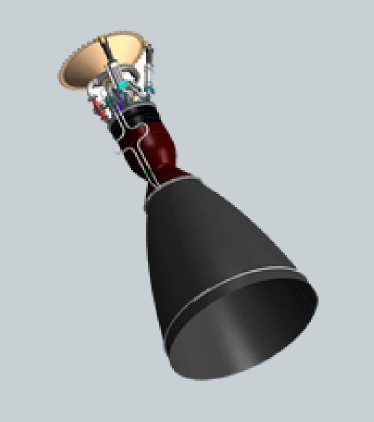
Kestrel engine

So the total amount of propellant burned during the parallel burn portion is that of the side booster(s) only. But the Schilling Calculator assumes the amount of propellant burned in the center core during the parallel burn is the same as the amount burned in each side booster. So enter in the Calculator for the booster propellant load a fraction of the actual propellant load of a core equal to the number of side boosters divided by the number of cores. So if you're using 2 cores with one used as a side booster enter in the Calculator booster column 1/2 the amount of the actual core propellant load. And if using 3 cores with 2 used as side boosters, enter in 2/3rds the actual core propellant load in the booster section. This will ensure the Calculator interprets the total propellant burned during the parallel burn portion is that of the actual side booster(s) only.
But you also want the Calculator to take the amount of propellant burned during the center core's solo burn portion of the flight as that of a full propellant load. Since it is already taking it to have burned the same amount as what the side boosters have burned during the parallel burn portion, add this amount onto the actual propellant load of a core and enter this into a first stage column of the Calculator. For the other specifications for both booster(s) and center core such as Isp, dry mass, and thrust enter in the actual values.
"Payload" refers to complete payload system weight, including any necessary payload attachment fittings or multiple payload adapters
This is an estimate based on the best publicly-available engineering and performance data, and should not be used for detailed mission planning. Operational constraints may reduce performance or preclude this mission.
Falcon 1 Upper Stage Based Orbital Launcher.
In the blog post "On the lasting importance of the SpaceX accomplishment" I suggested that SpaceX's low cost, commercial approach to developing the Falcon 9 will lead to this being emulated by other launch providers and then, eventually, to spaceflight becoming routine. However, ironically, it might turn out their simplest development and one they dispensed with will have the fastest effect towards making orbital access routine.
It's the Falcon 1 upper stage. Compared to the first stage and certainly compared to the Falcon 9, it's a rather simple stage only using a pressure-fed engine, the Kestrel.
Kestrel engine
Pressure-fed engines and stages are much easier to develop than pump-fed ones. For instance there are the rockets developed by Armadillo Aerospace, Masten Space Systems, and Garvey Spacecraft Corporation.
And this was also the case for the Project Morpheus lunar lander stage. In the blog post "The Morpheus lunar lander as a manned lander for the Moon", I discussed the NASA's Project Morpheus emulating a low-cost commercial space approach was able to develop two Morpheus landers for only $14 million. And actually the parts only costs were in the range of $750,000 per lander.
The construction costs for pressure-fed engines can also be low cost. For instance Project Morpheus was able to produce their engines at a cost of only $60,000:
NASA dreams of future Morpheus project templates.
March 14, 2015 by Chris Bergin
The main engine – which was also tested at the Stennis Space Center – could throttle at a ratio of 4 to 1, ranging between 1,400 and 5,400 pounds thrust. All Morpheus engines were custom designed and built specifically for Morpheus and only cost $60,000 each.
The specifications for the Falcon 1 upper stage are given here:
Falcon 1.
It has a 360 kg dry mass and 3,385 kg propellant mass, and a 3,175 kilogram-force vacuum thrust and 327 s vacuum Isp using the Kestrel engine. This is an upper stage engine however with a long nozzle that can't be used at sea level. In the post "Altitude compensation attachments for standard rocket engines, and applications" I described various attachments to be made to existing engines to give them altitude compensation ability.
However, since pressure-fed engines are so comparatively low-cost they could be designed from the beginning to have aerospike nozzles. There is for instance the aerospike engine of Garvey Spacecraft. And Firefly Space Systems will construct an aerospike nozzle by using numerous small engines arranged around a central spike.
The question though is how much thrust could be developed with the Kestrels at sea level using altitude compensation. I'll estimate from the formula for Isp for a rocket engine:
The ideal exhaust velocity is given by
where k is the specific heat ratio, R* is the universal gas constant (8,314.4621 J/kmol-K in SI units, or 49,720 ft-lb/(slug-mol)-oR in U.S. units), Tc is the combustion temperature, Mis the average molecular weight of the exhaust gases, Pc is the combustion chamber pressure, and Pe is the pressure at the nozzle exit.
http://www.braeunig.us/space/propuls.htm#Isp
The pressure factor at the end reduces the Isp at sea level. The specific heat ratio k is about 1.24 for kerolox. The Kestrel operates at a chamber pressure of 135 psi. Then the pressure factor is:
sqrt(1-(14.7/135)^(.24/1.24)) = .591. So the Isp at sea level is 327*.591 = 193 s and the sea level thrust is .591*3,175 = 1,876 kilogram-force.
Note for this estimate to be valid you have to have altitude compensation so that the engine has optimal performance at sea level, i.e., you don't have the back-pressure loss that results from non-optimal expansion.
Because of the 3,745 kg gross mass of the stage though, we need to reduce the propellant load to be loftable by the single Kestrel at the 1,876 kilogram-force sea level thrust. We'll reduce the propellant load by a factor of .45, so to .45*3,385 = 1,520 kg. We want also to maintain the relatively high mass ratio for the stage so we'll reduce the tank size. The tank mass is proportional to the propellant mass. Subtracting off the 52 kg mass of the Kestrel leaves us 308 kg in the stage dry mass. Multiplying this by .45 gives .45*308 = 138.6 kg. Adding on the 52 kg mass of the Kestrel gives a dry mass of 190 kg.
Other elements of a rocket stage such as the insulation, wiring, avionics do not scale linearly with propellant mass as does tank mass. However, since for pressure-fed stages the dry mass is so dominated by the tank mass this gives an approximate value of the stage mass when you scale down the stage size.
Moreover we can further reduce the dry mass by using composite propellant tanks. Microcosm, Inc. is making small-sized composite tanks that could be used for the purpose. NASA research has shown composite tanks can save 30% off the mass of aluminum-lithium tanks. Since Al-Li tanks save about 25% off the weight of standard aluminum tanks, this means composites can save about 50% off the weight of standard aluminum propellant tanks.
To estimate the mass this could save for this application, historically the propellant mass to tank mass ratio for kerolox for standard aluminum tanks is about 100 to 1. Note though this is for pump-fed engines that only need their stages at about 2 bar, about 30 psi. When the tank pressure is increased for pressure-fed engines the tank mass is correspondingly increased. The Falcon 1 upper stage tanks are kept at 200 psi pressure. So for our propellant mass of 1,520 kg, the tank mass assuming standard aluminum might be (1,520 kg/100)*(200 psi/30 psi) = 101 kg. Then a reduction of 50% in the tank mass would cut 50 kg from the dry mass to bring it to 140 kg. However, we'll calculate here the payload using 190 kg dry mass number, as the dry mass here is approximate since some components of the stage won't actually scale proportionally with the stage size.
Cross-Feed Fueling for Multiple Cores.
To increase payload we'll use cross-feed fueling. Note that cross-feed fueling is actually a well-understood technology, having been used on the Space Shuttle OMS engines:
Propellant Storage and Distribution.
"The propellant storage and distribution system consists of one fuel tank and one oxidizer tank in each pod. It also contains propellant feed lines, interconnect lines, isolation valves and crossfeed valves.
"The OMS propellant tanks of both pods enable the orbiter to reach a 1,000-foot- per-second velocity change with a 65,000-pound payload in the payload bay. An OMS pod crossfeed line allows the propellants in the pods to be used to operate either OMS engine."
And it has also been used for decades for jet airliners:
Concorde.
Balancing by Fuel-Pumping.
The Concorde Tank-Schematic:
"1 + 2 + 3 + 4 are the Collector-Tanks, feeding the engines directly. Usually they feed there counterpart engines – but they can be cross-switched to feed more and/or other engines at the same time.
5 + 7 and 8 + 6 are the Main-Transfer Tanks, feeding the 4 Collector-Tanks. Initially 5 + 7 are active. If those are empty 6 + 8 take over (or must be activated from the Engineering Panel!).
5a + 7a are Auxiliary-Tanks (to 5 and 7).
9 + 10 are the Trim-Tanks for balancing forward
11 is the Trim-Tank for balancing afterward"
To emulate rocket cross-feed fueling with the Schilling Launch Performance Calculator, note that during the parallel burn portion of the flight the propellant for the center core engines is coming from the side booster stage(s). This ensures that the center core will have a full propellant load during its solo burn portion of the flight, after the side booster(s) are jettisoned.
So the total amount of propellant burned during the parallel burn portion is that of the side booster(s) only. But the Schilling Calculator assumes the amount of propellant burned in the center core during the parallel burn is the same as the amount burned in each side booster. So enter in the Calculator for the booster propellant load a fraction of the actual propellant load of a core equal to the number of side boosters divided by the number of cores. So if you're using 2 cores with one used as a side booster enter in the Calculator booster column 1/2 the amount of the actual core propellant load. And if using 3 cores with 2 used as side boosters, enter in 2/3rds the actual core propellant load in the booster section. This will ensure the Calculator interprets the total propellant burned during the parallel burn portion is that of the actual side booster(s) only.
But you also want the Calculator to take the amount of propellant burned during the center core's solo burn portion of the flight as that of a full propellant load. Since it is already taking it to have burned the same amount as what the side boosters have burned during the parallel burn portion, add this amount onto the actual propellant load of a core and enter this into a first stage column of the Calculator. For the other specifications for both booster(s) and center core such as Isp, dry mass, and thrust enter in the actual values.
We'll calculate here the case for using two side booster of same size as the central core. Enter in the Schilling calculator the dry mass of 190 kg for the boosters and the first stage, which is the central core. For the thrust and Isp for the boosters and the first stage, enter in the vacuum Isp of 327 s and vacuum thrust of 31.1 kN in the calculator. However, to emulate cross-field fueling, for the propellant fields enter in (2/3)*1,520 kg = 1,013 kg in the booster section and 1,013 kg + 1,520 kg = 2,533 kg in the first stage section. Choose Cape Canaveral as the launch site and 28.5 degrees as the launch inclination to match the latitude for the launch site. For the "Restartable Upper Stage" select "No", otherwise the payload will be reduced. Then the calculator gives the result:
| Launch Vehicle: | User-Defined Launch Vehicle |
|---|---|
| Launch Site: | Cape Canaveral / KSC |
| Destination Orbit: | 185 x 185 km, 28 deg |
| Estimated Payload: | 63 kg |
| 95% Confidence Interval: | 19 - 116 kg |
"Payload" refers to complete payload system weight, including any necessary payload attachment fittings or multiple payload adapters
This is an estimate based on the best publicly-available engineering and performance data, and should not be used for detailed mission planning. Operational constraints may reduce performance or preclude this mission.
We could get over 100 kg if we used three side cores.
Methane for Improved Performance.
We could also increase the payload using methane instead of kerosene as the fuel. For booster stages, methane has about the same performance as kerosene since the greater density for kerosene makes up for its lower Isp. But for upper stages methane offers better performance since it would give a lighter stage that had to be lofted by the lower stages. So if you wanted to use identical stages for simplicity and cost, methane would be the preferred fuel.
There is also a key practical reason why methane might be preferred. NASA has developed the methane-fueled engine for the Morpheus rocket stage. With NASA's Technology Transfer program the technical info on the engine would also be shared at least for American companies. Then you would only have to pay the ca. $60,000 construction costs for the engine.
Considering that both the Kestrel and Morpheus engines are reusable this already low cost launcher can cut the cost to space considerably. It then could be used for DARPA's proposed reusable launchers discussed here: "NASA Technology Transfer for suborbital and air-launched orbital launchers." In an upcoming blog post I'll also show that using a single one of these cores, it can be used as either the reusable first stage booster, or the air-launched orbital stage for these DARPA programs.
Scale-up to Large Launchers.
Note this is a 5,130 gross mass launcher to launch a 63 kg payload. Pressure-fed stages scale up more easily than pump-fed ones since you don't have the complexity of creating a turbopump for the larger size engines. The Mercury spacecraft that carried John Glenn massed 1,300 kg. Using modern materials we could probably make a one-man capsule for 500 kg. Then we would only have to scale up our 3 core launcher by a factor of 8 to launch a one-man capsule to orbit. This would be a 41,000 kg gross mass launcher compared to the 120,000 kg gross mass Atlas rocket that launched John Glenn to space.
Bob Clark


10 comments:
Scale up by 8 - does that mean an engine 8 times as large is needed? Or would 8 (or 9) of these engines do the job?
It could work either way. Note though that pressure-fed engines are easier to scale-up without the complexities of turbopumps. For instance the Seadragon design of the 60's would have used a single pressure-fed engine of 80 million pound thrust(!) to get 550 metric tons to orbit:
Sea Dragon.
https://en.m.wikipedia.org/wiki/Sea_Dragon_(rocket)
Bob Clark
I would call into question the accuracy of Townsend method approximation to what is essentially a SSTO with boosters. Specifically the ISP fluctuation. It uses an estimation of how much "ISP at sl" drag there is according to vacuum figure and historic launchers. Thing is, no historic 1st stage or booster has 40% difference between vacuum and sl rating. Ok, except for Vulcain, but it only gives 8% liftoff thrust.
Sea dragon concept could put about 3% of its liftoff weight into orbit. And it used hydrogen upper stage, and 20 bar first stage combustion chamber pressure. Stage dry weight was only slightly heavier.
If Sea dragon upper stage had 420isp (320 is probably a typo), the first stage isp has to be downgraded to 220 to keep the same payload. Using kerosene upper stage with 327isp drops payload to 20%...
By "Townsend" method are you referring to the Schilling calculator? NASA has made available its trajectory calculation software which undoubtedly would be more accurate but it is very un-userfriendly.
The great difference between the sea level and vacuum thrust and Isp values quite likely would effect the accuracy of the Schilling calculator. However, there is the additional factor that I am assuming altitude compensation which will act to improve the payload.
Bob Clark
Yes i was reffering to a calculator you used. Altho it is great it does not differenciate between various engines. Like the NK33 which has vacuum isp of 331s, only slightly better than kestrel. But its sl isp is 297s...
My favourite altitude compensation is the one aerojet developed. Cant remember the exact name atm, but it was adding fuel mix inside the nozzle to prevent flow separation and increase thrust.
This method would be prefered over extendable nozzle. As extendable nozzle does not add to thrust at low altitude.
As far as i know main problem with oversized nozzles is flow separation and thus bigger chance for the nozzle to destroy itself.
I develop advanced new materials, with roughly ten times the strength to weight ratio of anything currently being tried. The main advantage is not strength but stiffness. These materials control loads and deflection much better than anything in the past. The stiffness usually cuts down on vibration.
I say "usually" because at certain frequencies we measure harmonics that are in tune with the micro-structure of the material. In these cases vibration goes up.... way up! The explosions are impressive, it literally shatters aluminum at a molecular level. There is nothing left but dust.
We tried to change the harmonic phenomena by heating/cooling the affected metals. But this was totally impractical from an energy budget standpoint. It wasted way too much energy heating/cooling parts, which invariably lead to lower specific impulse. Not good.
Next we tried tuning the materials to specific frequencies. This didn't work either, but it did make some awfully strange sounds. Metals don't typically make sound, unless it's a bell. The sounds generated by the vibrations in the aluminum kept ringing, like a tuning fork, for a really long time. Very strange. I've never found a good explanation for this phenomenon.
Best Regards, North
Thanks for the info. If the harmonics are due to periodic structure, perhaps you can alter it in random ways to disrupt the harmonics.
Bob Clark
Theatres used to have sound problems due to the columns supporting the roof acting as diffraction gratings. Architects solved the problem by simply changing the distance between the columns by a different number of inches each time. With the columns out of tune the sound was no longer concentrated.
By changing thickness, length, shape, smoothness and/or backing material it may be possible to reduce the harmonic effects.
Frickin idiot. Can't use Sea Dragon as an example. It was never built or tested.
Also, your point about crossfeed is dead wrong. Shuttle OMS or airliner fuel tanks are not relevant examples and hence not a "well understood technology". They don't involve the same flow rates, cryogenics or inflight disconnects. Nor is the plumbing right at the engine inlets.
You are doing a disservice by posting blatantly wrong information in this blog.
Armadillo Aerospace also used cross-feed fueling on their vernier thrusters on their Quad rocket:
Quad (rocket).
"The cold gas vernier engines are cross-fed by gas drawn from ullage space of the opposite tank. The vehicle was able to transfer propellant through connecting pipes between opposite tanks by controlling ullage pressures with the thrusters; this helps it balance, minimizing gas use."
https://en.wikipedia.org/wiki/Quad_(rocket)
Also inflight disconnects was used on the earliest orbital U.S. rocket, the Atlas that first orbited John Glenn to space. The Atlas used two outboard high thrust engines, and a central low thrust, but high Isp engine.
However, the Atlas could not reach orbit with the heavy, high thrust engines. So it jettisoned them in flight. All three engines though used the very same propellant tank. So inflight disconnects were required.
Post a Comment