Thursday, December 28, 2017

Altitude compensation attachments for standard rocket engines, and applications, Page 6: space shuttle tiles and other ceramics for nozzles. UPDATED: 3/6/2018

Copyright 2017 Robert Clark


Some possibilities for altitude compensating nozzles include actual adjustable-sized nozzles but using non-flexible materials such as ceramics. In such cases the high expansion ratios needed for optimized expansion at high altitude would give nozzles of impractical size, for instance they wouldn't fit within the width of the rocket stage.

A couple of possibilities for dealing with this eventuality:


And:


Vacuum optimized nozzles, whether altitude compensating or not can take a great deal of mass of an engine or stage. See for example the specifications of the Star 48B here:


You see the weight of the nozzle assembly is nearly that of the case assembly. This would become even more of a weight problem with extreme expansion ratios of hundreds to one. 

 The lightweight space shuttle underside tiles may provide a solution. Their volume density is only 0.144 gm/cm^3. And according to this report their areal density is 1.19 gm/cm^2:

TPS Materials and Costs for Future Reusable Launch Vehicles.

 The AETB-8/TUFI listed is a toughened tile material that has higher impact resistance while maintaining the same temperature resistance.

 Judging from the size of the size of the Star 48B nozzle, the nozzle weight might be reduced from 90 lbs to ca. 20 lbs using the AETB-8/TUFI tiles.

 A possibly even more lightweight material was developed by aerospace engineer/mathematian GW Johnson. He described it in this video presentation at the 16th Mars Society conference in 2013:

Reusable Ceramic Heat Shields - GW Johnson - 16th Mars Society Convention.

 Johnson estimated the volume density as only 0.03 gm/cm^3, a third that of the shuttle tiles. Also interesting is that Johnson originally developed the material to act as insulation for ramjet combustion chambers. 

 Note that even the insulation in the Star 48B solid motor is a sizable weight at 60 lbs, compared to the 129 lbs casing weight. Then Johnson's ceramic might also be able to be used as a lightweight replacement for solid motor insulation.

  Bob Clark 

UPDATE, 3/6/2018

 A problem though is the shuttle tiles and also the Johnson tiles have low tensile strength, only about 1 bar. This probably can be improved by adding strengthening bars to the ceramic as steel rebar is used to improve the strength of concrete.

 Additionally, as the exhaust travels down a nozzle towards the exit the pressure also decreases. So perhaps it could be used as the nozzle extension for the nozzle below where the exhaust gas falls below 1 bar pressure. This could result in a significant reduction in weight. See for instance the comparison size of the RL10 nozzle used on the DC-X optimized for low altitude flight compared to one for high altitude, near vacuum flight:


 This might be hard to test though for amateurs. Amateurs don't have access to the expensive test equipment used to test engine performance under high altitude, near vacuum conditions.

 To do the test at sea level we would need to make the attachment so that the length of the nozzle would make the exit pressure to be quite low. This then entails dangerous loads on the nozzle due to the overexpansion at sea level ambient pressure. This would be made even worse due to the brittle nature of the ceramic.

 The most effective test would be on the rockets by university and amateur teams whose rockets have reached 100K feet. The pressure there is only about 1% that of sea level.

 The problem with getting a material to work is that it has to be both high temperature and lightweight. But what if it didn't have to be high temperature?

 I was puzzled by these images showing the nozzle extensions on rocket engines glowing red hot while firing:

RL-10B2 engine with nozzle extension.


Merlin Vacuum engine with nozzle extension.

  But when the exhaust extends down a nozzle it both expands and cools. So why were these nozzle extensions glowing red hot?

 Perhaps they get red hot because they are heated by conduction by the upper parts of the nozzle where the exhaust gas is still hot.

 If so, then we could use the ceramic tiles as insulation between the upper part of the nozzle, and the attached nozzle extension. In that case the nozzle extension would need to be as heat resistant and there would be many more materials that would have the lightweight characteristic required.

Tuesday, October 24, 2017

A Small Raptor Spaceship.

Copyright 2017 Robert Clark

 In the blog post "SpaceX BFR tanker as an SSTO", I suggested the BFR tanker could as an expendable SSTO get a comparable payload to orbit as the Falcon Heavy at ca. 50 metric tons.  SpaceX however wants to move to reusables. But Elon in his presentation on the BFR suggested the BFR tanker as a reusable SSTO might get less than 15 metric tons to orbit.

 This large loss in payload when switching to reusable is due to the large amount of propellant that must be kept on reserve for the vertical, propulsive landing. I argued then for using winged, horizontal landing to retain most of the payload of the expendable case, perhaps only a 10% drop from ca. 50 tons to ca. 45 tons.

 This would be different from the SpaceX preferred vertical landing method. But the production of a routine manned orbital flight capability is so important it should be implemented even if it would require completely different spaceships for the orbital flight and interplanetary flight uses.

 There is also the fact that if it does prove to be the case that switching to a winged, horizontal landing allows most of the expendable SSTO payload to be retained, then this may also be the case for the full two-stage BFR. Then instead of losing 100 tons off the expendable 250 ton payload to only 150 tons as reusable, a 40% loss, perhaps only 10% would be lost, so a 225 ton reusable payload. 

 This would be important for maintaining high payload with reusability both for the SSTO and full two-stage cases. But both of these are high payload launchers at ca. 45 and 225 tons. But SpaceX has spoken of moving all their launchers to the Raptor engines. In that case SpaceX needs a small launcher.

 We could make it half-size to the BFR upper stage. However, to give it flexibility to also be used as a upper stage we'll make it one-quarter size, at a ca. 275 ton propellant load. A first level estimate would put the dry mass at 1/4th of the BFR tanker dry mass so at 50/4 = 12.5 metric tons. But as mass ratio improves as you scale up a rocket, so also does it reduce as you scale a rocket down. Then as a second level estimate we'll take the scaling relationship as Elon did in his presentation on the BFR.

 Elon cited the dry mass of the BFR spaceship as 85 tons, a factor of 85/75 = 1.13 times more than just by proportional scaling. However, this small size stage is 1/4th size, not just half-size. So we'll apply this scaling factor twice, i.e., by the factor 1.13^2 = 1.28. Then we'll take the dry mass as 1.28*12.5 = 16 tons. 

 This can be lofted by two of the Raptor engines with a total sea level thrust of 2*1,700,000 N = 3,400,000 N = 347,000 kilogram-force. Now use the Schilling launch vehicle performance calculator to estimate the payload. The estimator takes the vacuum Isp and thrust values so 375 s Isp and 2*1,900,000 N = 3,800,000 N total thrust.

 Then the input screen appears as:


 And the results appear as:


A payload of ca. 8,100 kg as an expendable SSTO. Using the 10% payload loss estimate for a winged reusable, this would be ca. 7,300 kg as a reusable SSTO. 

 This might be enough to carry the manned Dragon 2 to orbit as a reusable SSTO. Based on its size being 1/8th that of the ITS upper stage, which has a $130 million production cost, we can estimate the production cost of this SRS as $16 million, and keep in mind it is intended to have hundreds of flights. We can imagine then private individuals purchasing their own small, reusable launchers to orbit.

 Moreover, Elon has spoken of doing short hops of the BFR upper stage to test the point-to-point transport capability. A quarter-scale version would allow this to be tested with less financial risk. Such a smaller test vehicle would also allow you to test more cheaply alternative return methods such as winged, horizontal landing. This test vehicle if successful could then go right to production for use by SpaceX for launches they sell, or for selling to individuals for conducting their own launches.

 To increase the payload, we may want to add another engine. After giving the dry mass an additional 1,000 kg, and raising the total thrust to 5,700,000 N because of the third engine, the input screen appears as:


 And the results are:


 A 9,700 kg expendable SSTO payload. After a 10% reusable payload loss, the reusable SSTO payload would be 8,700 kg. This higher payload may be necessary for the Dragon 2 to also carry the launch abort system.


Two-stage case.
 We'll calculate now the payload using the BFR tanker as the booster and the SRS as the upper stage.
The input page now looks like:


And the results page looks like:


Methods of increasing take-off thrust.
 One issue with this two-stage rocket though is the low liftoff thrust/weight ratio when carrying the upper stage might make the actual payload less than that indicated by the calculator. So we'll explore some possibilities of increasing the take-off thrust. One possibility is a thrust scale up. For instance the Merlin Full Thrust is at about a 15% increase above the rated thrust value of the Merlin 1D. And the SSME had a maximum thrust value 9% above its rated value.

 However, another possibility is a recent research advance in engines known as "thrust augmentation nozzle", TAN. It's sort of like an afterburner for rocket engines. What it does is inject propellant into the nozzle and ignites it to generate additional thrust. See discussion here:

Thrust Augmented Nozzles
Posted on November 12, 2007 by Jonathan Goff

http://selenianboondocks.com/2007/11/thrust-augmented-nozzles/

 In experiments the researchers were able to increase thrust by up to 70%.

 It is notable that TAN also serves as a method of altitude compensation for it allows larger, vacuum optimized nozzles to also be used at sea level by preventing separation by conducting combustion also in the nozzle. Some method of altitude compensation should be used to optimize performance both at sea level and vacuum rather than making trades of which combination of sea level, mid level, and vacuum engines to use. Some possibilities to do the altitude compensation, though not the liftoff  thrust increase, are discussed at, [1], [2], [3], [4], [5].

 A variation on TAN may allow also to increase the effective Isp at sea level. The idea behind the variation is to use atmosphere air as the oxidizer for the augmented thrust combustion.

We will need to bring the atmospheric air into the nozzle to burn with the fuel. One possibility is indicated here:

Rocket motor thrust nozzle with means to direct atmospheric air into the interior of the nozzle.
US 3469787 A.

 We would open up vents on the nozzle to allow air to flow in, then burn it with the fuel. We would have to insure the vents we opened were further down on the nozzle so that the reduced pressure of the exhaust flow further down would allow the atmospheric air to enter in. We also don't want after we ignite the fuel with the air for this exhaust to exit back out the vents, further reason for making the opened vents to be further down the sides of the nozzle.

  Another implementation of this idea would use the aerospike nozzle.


 The fuel would be emitted from the sides of the aerospike lower down on the spike where the exhaust pressure is lower and the ambient air pressure would constrain the combustion.

 A problem with both the vented nozzle and aerospike implementations though is the pressure of combustion would be at most one bar. This would limit the thrust produced. Still, it may be the mass of nitrogen heated along with the oxygen might permit sufficient thrust production.

 Another possibility is to use a vapor-air detonation as the combustion method. This will permit high exhaust speed for the combustion:

Methane-Air Detonation Experiments at NIOSH Lake Lynn Laboratory.
https://www.cdc.gov/niosh/mining/userfiles/works/pdfs/madea.pdf


  Bob Clark


REFERENCES.
1.)Altitude compensation attachments for standard rocket engines, and applications.
http://exoscientist.blogspot.com/2014/10/altitude-compensation-attachments-for.html

2.)Altitude compensation attachments for standard rocket engines, and applications, Page 2: impulse pressurization methods.
http://exoscientist.blogspot.com/2016/01/altitude-compensation-attachments-for.html

3.)Altitude compensation attachments for standard rocket engines, and applications, Page 3: stretchable metal nozzles.
http://exoscientist.blogspot.com/2016/06/altitude-compensation-attachments-for.html

4.)Altitude compensation attachments for standard rocket engines, and applications, Page 4: the double aerospike.
http://exoscientist.blogspot.com/2016/10/altitude-compensation-attachments-for.html

5.)Altitude compensation attachments for standard rocket engines, and applications, Page 5: metal foil expandable nozzles.
http://exoscientist.blogspot.com/2017/08/altitude-compensation-attachments-for.html


Sunday, October 22, 2017

SpaceX BFR tanker as an SSTO.

Copyright 2017 Robert Clark

 Elon Musk has suggested the development of orbital point-to-point manned transport may pay for the development of his Mars colonization plans, the idea being there would be a great market for such manned flights. Peter Diamandis has made this point as well, that there would be a great market for such flights to orbit:

Peter Diamandis: Taking the next giant leap in space.


 Elon suggests such orbital transports would be best implemented as two-stage vehicles. However, this simulation shows the upper stage of the SpaceX Interplanetary Transport System (ITS) introduced by Elon Musk in 2016 could get a total 190 metric tons to orbit as an expendable SSTO, including the stage and the payload:


 Since the stage was estimated to weigh 90 tons, this would mean 100 metric tons payload as an expendable SSTO. Then the question is how much mass would be taken up for propellant for return using vertical landing.

 However, in the latest incarnation introduced in 2017 the upper stage of the now BFR is about half as large in propellant load and with 6 engines instead of 9. Here are screen grabs from the video on the latest version:


  So we may estimate this half-size version to have half the dry mass at ca. 45 metric tons and could get approx. 50 metric tons to LEO as an expendable SSTO.

 As justification for this dry mass estimate, here's the description of the original ITS upper stage, both spaceship and tanker versions:


 And here's the description of the BFR spaceship, half size to the ITS version:


 You see the BFR spaceship is at about half the listed dry mass value as the ITS spaceship.  Actually during the video Musk says the design mass was just at half at 75 tons, but the 85 tons mass was allowing for weight growth. So it is plausible the BFR tanker is ca. half the mass of the ITS version or a little more, ca. 45+ tons.

 We'll give it 9 engines instead of 6 so it'll have enough thrust to lift off with the heavy payload, and give it a dry mass of 50 metric tons with weight growth. Now do a payload estimate using Dr. John Schilling's launch performance estimator. The high expected thrust/weight ratio for the Raptors means they'll weigh perhaps 1,000 kg each. So the addition of 3 will add perhaps 3 tons to the dry mass. Since the payload is so high this will be a relatively small payload loss.

 The Schilling estimator takes the vacuum values for the Isp and thrust, so enter 375 s as the Isp and 9*1,900 kN= 17,100 kN for the total thrust.

 Insure that the "Restartable upper stage" option is set to "No" otherwise the payload will be reduced. And set the launch inclination to match the launch site, so at 28.5 degrees for Cape Canaveral:


 Then the result is:


 Confirming the ca. 50 metric ton payload as an expendable SSTO.

 But this puts it as an expendable SSTO in the payload range of the expendable Falcon Heavy while being also in the same size range of the Falcon Heavy. So this SSTO would get the same payload fraction as a 2 and 1/2 stage vehicle. Moreover, judging from the fact the ITS tanker upper stage was to cost $130 million production cost, the half size BFR tanker might only be $65 million, so it would be half the cost of the Falcon Heavy. But the Falcon Heavy as an expendable launcher already would be a significant cut in the cost to orbit. So the BFR tanker as an expendable SSTO could be a great reduction in the cost to space, compared to current values.

 I had earlier done a calculation that showed the Falcon Heavy as an expendable with 53 metric ton payload capacity and $125 million launch cost could be financially feasible as a tourism vehicle to orbital space or transport to orbital space hotels:

Falcon Heavy for Orbital Space Tourism.
http://exoscientist.blogspot.com/2014/09/falcon-heavy-for-orbital-space-tourism.html
 ​
 So this BFR tanker could likewise be feasible financially as an expendable SSTO, as the price should be well less than $125 million as an expendable. But of course SpaceX wants to make it reusable. The reusability should cut the launch cost multiple times. Then the question is how much will reusability cut into the payload mass?

Reusable SSTO case.
  In the presentations on the ITS and BFR both the spaceship and tanker versions of the upper stage were always presented as reusable. So it is likely the heat shield mass is already included in the cited vehicle dry mass values. I'm estimating though surprisingly high values for the thermal protection of the BFR upper stages, either spaceship or tanker versions. I'm using the fact as indicated in the wiki page on the BFR that it will use the PICA-X thermal protection material. Several references give the PICA-X density as about 0.25 gm/cc = 250 kg/m3, and the thickness as on the Dragon 2 as 7.5 cm, 0.075 m, about 3 inches.

 The BFR upper stage has a length of 48 meters and a width of 9 meters. The top part of the stage is conical. Visually, this top portion is about 1/3rd the vehicle length, so about 16 meters long. So I'll approximate the bottom area to be covered by thermal protection covered as 32*9 + (1/2)*16*9= 360 m2.

 Then the volume of the thermal protection material is 360 * 0.075 = 27 m3. At a density of 250 kg/m3, that amounts to a mass for the thermal protection of 27 * 250 = 6,750 kg, which is a surprisingly high included mass in the dry mass of 85 tons for the spaceship upper stage or the 50 tons for the tanker upper stage.

 One possibility, is the thickness of the PICA-X for the Dragon 2 is coming from the fact it is doing a ballistic reentry, thus generating high heat. However, the BFR upper stage will be doing a more gentle gliding reentry. So perhaps the thermal protection will only need to be half as thick, so weigh half as much. For instance, the heat shield tiles on the underside on the space shuttle only weighed half the PICA-X tiles.

 And new versions of these space shuttle tiles used on the X-37B are more durable while remaining lightweight:

The X-37B stands in front of part of the fairing that protects it during launch, showing off the silica tiles on its underside. Those TUFI (toughened uni-piece fibrous insulation) tiles are said to be more durable than their counterparts on the space shuttle. On the leading edge of the wings, meanwhile, are TUFROC (toughened uni-piece fibrous refractory oxidation-resistant ceramic ) tiles, which NASA named the government winner of its 2011 Invention of the Year Award.

 Elon has implied the reusable version of the BFR upper stage would only get perhaps in the range of 10 to 15 metric tons payload (by saying it's an order of magnitude less than the full BFR 150 ton reusable payload.) That loss in payload is not coming from the heat shield mass since that's already included in the vehicle dry mass. The loss in payload is high though, 40 tons, nearly the size of the entire vehicle dry mass, presumably because of the amount of the propellant that needs to be kept on reserve for landing on return.

 I'd like to see a trade study of the payload of instead going with wings for a horizontal landing. See for example the discussion here:

http://yarchive.net/space/launchers/horizontal_vs_vertical_landing.html

 Wings typically take up only 10% of an aircraft dry mass. Then with carbon composites, that would be cut to less than 5% of the landed (dry) mass. Keep in mind the loss in payload with vertical, propulsive landing is nearly 100% of the vehicle dry mass. Also, going with short, stubby wings as with the X-37B, you can make the wing weight even less:


 The areal size of the wings in that case would also be less than that of bottom area of the BFR tanker, perhaps only 1/4th to 1/3rd the areal size. So the increase in heat shield mass would only be at most 1/3 that of the approx. 6,750 kg mass of the current heat shield, so perhaps an extra 2,250 kg. But actually the addition of wings gives a gentler glide slope so probably the heat shield thickness could be reduced. The result might even be the total heat shield mass would be reduced by adding wings.

 Elon has spoken of preferring vertical landing because it could be used generally on both worlds with and without atmospheres. However, to achieve his desired goal of making mankind multiplanetary, making human orbital spaceflight commonplace is an important part of that goal. A lower development and production cost BFR upper stage acting as a reusable SSTO would go a long way towards that goal. So even if the optimized orbital or point-to-point transport looks completely different than the interplanetary lander, such as requiring wings for example, it would still be important to develop it.

 Advantage of altitude-compensation.
 In the discussion after the introduction of the BFR, Elon Musk and other commenters on various space forums, engaged in alot of speculation on the optimal combination of sea level engines, vacuum engines, and some medium, intermediate area ratio engines. This is necessitated because the highest Isp engines, optimized for vacuum, can not operate reliably, and safely at sea level. But then using sea level engines or even intermediate level engines would subtract from the Isp possible.

 This illuminates once again the importance of implementing altitude compensation engines in space flight, at least for Earth launch. This would permit the high thrust needed at launch at sea level, as well as the high Isp needed at near vacuum.

 There are many ways to implement the altitude compensation and none are particularly difficult to do. Some methods are discussed here [1], [2], [3], [4], [5].


REFERENCES.

1.)Altitude compensation attachments for standard rocket engines, and applications.
http://exoscientist.blogspot.com/2014/10/altitude-compensation-attachments-for.html

2.)Altitude compensation attachments for standard rocket engines, and applications, Page 2: impulse pressurization methods.
http://exoscientist.blogspot.com/2016/01/altitude-compensation-attachments-for.html

3.)Altitude compensation attachments for standard rocket engines, and applications, Page 3: stretchable metal nozzles.
http://exoscientist.blogspot.com/2016/06/altitude-compensation-attachments-for.html

4.)Altitude compensation attachments for standard rocket engines, and applications, Page 4: the double aerospike.
http://exoscientist.blogspot.com/2016/10/altitude-compensation-attachments-for.html

5.)Altitude compensation attachments for standard rocket engines, and applications, Page 5: metal foil expandable nozzles.
http://exoscientist.blogspot.com/2017/08/altitude-compensation-attachments-for.html

Tuesday, August 22, 2017

Orbital rockets are now easy, page 2: solid-rockets for cube-sats.


Copyright 2017 Robert Clark

Introduction.
  In the blog post "Orbital rockets are now easy", I argued that with altitude compensation, liquid-fueled orbital rockets become within the capabilities of most university undergraduate labs.

 Here I'll argue solid-fuel rockets can also be built by amateurs to reach orbital space.

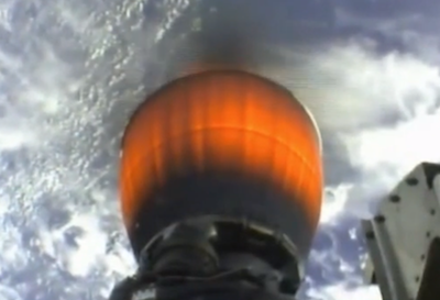
 I was impressed by this university teams launch to 144,000 feet of a suborbital solid-fuel rocket:

USC Rocket Propulsion Laboratory Breaks Record.
Amy Blumenthal | March 16, 2017
Student-run RPL launches rocket of own design to 144,000 feet.

LAUNCH OF FATHOM II ON MARCH 4, 2017. AT 144,00 FT FATHOM II WAS THE HIGHEST ALTITUDE FOR A ROCKET ENTIRELY DESIGNED AND MANUFACTURED BY STUDENTS
https://viterbischool.usc.edu/news/2017/03/usc-rocket-propulsion-laboratory-breaks-record/

  However, using essentially "off-the-shelf" components, you can get a 3-stage solid rocket of comparable size to actually reach orbit. Moreover, I was surprised to see after running a launch simulation program that you don't even need altitude compensation to accomplish it.

 By essentially off-the shelf, you could use solid-rocket motors sold to amateurs but with an addition of a lightweight carbon-composite casing that amateurs such as the USC team already have been making themselves for their own rockets.


 You would have Cesaroni Technology, or other solid motor manufacturer, make their motors with only a thin aluminum case, not meant to hold the full combustion chamber pressures. The amateurs would then make the carbon composite case rated for the full combustion chamber pressure.

 Cesaroni also makes commercial sounding rockets with carbon composite casings but this is likely to be more expensive than if the amateurs make it themselves.

Specifications.
 This motor by Cesaroni Technology, or similar motors by other manufacturers, could form the basis of the orbital rocket:


  This motor though only has a mass ratio of about 2.5 to 1, adequate for amateurs doing high power rocketry test flights, but not for an orbital rocket. However, you can save about half of the weight of the aluminum casing used by replacing it by carbon composite.

 Cesaroni was able to do this for the suborbital rocket SpaceLoft they constructed for UP Aerospace, Inc.:

CTI rocket motor successfully powers the launch carrying the ashes of astronaut and James Doohan - April 30, 2007.
On April 28th, a Spaceloft™XL rocket successfully completed a round-trip space flight launched from Spaceport America. This rocket was developed by UP Aerospace Inc. of Hartford, Conn. The rocket carried a wide variety of experiments and payloads, which included the cremated remains of Star Trek's "Scotty", James Doohan and NASA astronaut and pioneer Gordon Cooper. In addition, the cremated remains of more than 200 people from all walks of life were onboard. Also flown into space on the SL-2 Mission were dozens of student experiments from elementary schools to high schools to universities - from across America and worldwide - as well as innovative commercial payloads.
The flight was a successful demonstration of the rocket motor developed and built by Cesaroni Technology Incoporated (CTI). CTI started the design process in September of 2005. CTI specializes in low cost propulsion systems for military and space applications and used its experience to develop an affordable, reliable propulsion system for the rocket. The motor has a carbon fiber composite case and a monolithic solid propellant grain that is bonded to the casing.
Watch the post-launch coverage as carried by local television station KRQE here (9 Mb)
Watch the launch as carried by the BBC here (1 Mb)
Watch pre-launch coverage as carried by CTV Toronto here (9 Mb)
Watch pre-launch coverage as carried by CBC Toronto here (9 Mb)
Technical data for the UPA-264-C rocket motor


 So we'll assume the Cesaroni Pro150 can get a 0.8 propellant fraction by using carbon composite casing. We'll round off the propellant mass to 20 kg, and take the dry mass as 5 kg. We'll take this as the third stage of our rocket.

 For the lower stages, the size of stages commonly are in the range of 3 to 5 times larger than the succeeding stage. We'll take the second stage as 4 times larger than the third stage at a 80 kg propellant weight and 20 kg dry weight. For the first we'll take it as larger by an additional factor of 4 to a 320 kg propellant weight and 80 kg dry weight.

 Now for the specific impulses for the stages. This commercial solid motor has a similar sea level Isp as the Cesaroni solid rocket motor Pro150:

Star 37.
Thiokol solid rocket engine. Total impulse 161,512 kgf-sec. Motor propellant mass fraction 0.899. First flight 1963. Solid propellant rocket stage. Burner II was a launch vehicle upper stage developed by Boeing for the Air Force Space Systems Division. It was the first solid-fuel upper stage with full control and guidance capability developed for general space applications.
AKA: Burner 2;TE-M-364-1. Status: First flight 1963. Number: 180 . Thrust: 43.50 kN (9,779 lbf). Gross mass: 621 kg (1,369 lb). Unfuelled mass: 63 kg (138 lb). Specific impulse: 260 s. Specific impulse sea level: 220 s. Burn time: 42 s. Height: 0.84 m (2.75 ft). Diameter: 0.66 m (2.16 ft).
Thrust (sl): 33.600 kN (7,554 lbf). Thrust (sl): 3,428 kgf.
http://www.astronautix.com/s/star37.html

 So we'll estimate the vacuum Isp of the Cesaroni Pro150 to be in the Star 37's range of 260 s. However, rocket stages can get higher vacuum Isp's by using longer nozzles. A 285 s Isp is not uncommon for solid rockets motors with vacuum optimized nozzles, such as the Star 48.

 So we'll take the Isp for the second and third stage as 285 s.

 For the thrust, we'll take the thrust of the third stage as the same as the Pro150 of 8 N, and assume the thrust for the second and first stage scale according to their size so to 32 N and 128 N, respectively.

 Now use Dr. John Schilling's launch performance calculator to estimate the payload.

 The input page looks like this:


 Note there some quirks of this program you need to be aware of if you use it. First, always use the vacuum values for the Isp's and thrust numbers, since the program already takes into account the diminution at sea level. Second, always set the "Restartable Upper Stage" option to "No", rather than the default "Yes", otherwise the payload will be reduced. Third, always set the launch inclination to match the launch site latitude, otherwise the payload will be reduced. This is related to the fact that changing the orbital plane involves a delta-v cost. So for the Cape Canaveral launch site, the launch inclination should be set to 28.5 degrees.

Now, here's the result:


 So a payload to LEO of 7 kg. And this with standard nozzles, no altitude compensation required.

Structure.
  To save costs, I'm envisioning making the components as much "off-the-shelf" as possible. But among its standard products Cesaroni offers the Pro150 as the largest motor. So to get the larger second and first stages, we would have to combine multiple copies of this motor.

  I could cluster them in parallel, but for the first stage that would be 16 of them, and you would have the problem of simultaneous ignition with that many motors.

  So what I'm envisioning is take 4 copies of the Pro150 stacked vertically one on top of the other for the second stage, then cluster 4 of these second stage motors in parallel for the first stage.

 The question is though about the vertical stacking is how much the thrust scales in this case. If for the solid motors the propellant burned from the bottom upwards, then the thrust would be the same as for a single motor, you would just get 4 times longer burn time.

  But that's not how large solid motors work. Actually, they have a hollow region in the center so the propellant burns from the inside surface, proceeding outwards. In this case, you have a greater amount of propellant being burned per second because of the larger vertical surface area with the stacked segments. In fact, the thrust scales linearly with the number of segments.

 By the way, the reason why I don't just also stack the first stage vertically, is because of the thinness of the rocket that would result. The Pro150 is about 3 feet long and 1/2 foot wide. If you stacked vertically 16 for the first stage, 4 for the second, and 1 for the third, that would be a rocket 63 feet high but only 1/2 foot wide, for a ratio of length to width of over 120 to 1.

 This ratio of length to width is called the "fineness ratio". Rocket engineers don't like for it to be higher than about 20 to 1 because of the severe bending loads that would result. The upgraded version of the Falcon 9 has been noted for its long, skinny profile, and has a fineness ratio of about 20 to 1. The Scout solid rocket had a fineness ratio of about 24 to 1. Solid rockets can support a higher fineness ratio because their thicker walls can withstand higher loads. Still, 120 to 1 would very likely be too high.

  So to avoid this I decided to form the first stage by clustering in parallel four copies of the second stage. Note here these four clustered motors arranged around the second stage will provide the full thrust for the first stage while the central second stage motor will not fire until the four clustered motors are jettisoned.

 It would be possible though to get a single vertically stacked motor using multiple segments if the segments were shorter, resulting in a smaller rocket. For instance, there is a market for cubesats at only 1 kg mass to orbit. If you made the solid motor segments only about 1/2 foot long by cutting the Pro150 into 6 segments, you could take one of these smaller segments as the third stage, 4 segments for the second stage, and 16 segments for the third stage.

Cost.
 The Cesaroni Pro150 retails for about $3,000 and in general the Cesaroni solids cost in the range of $100 per kg of the motor mass:

Cesaroni O8000 White Thunder Rocket Motor.   
$3,099.95
Product Information
Specification
Brandname:  Pro150 40960O8000-P                  Manufacturer:  Cesaroni Technology
Man. Designation:  40960O8000-P                    CAR Designation:  40960 O8000-P
Test Date:  4/10/2008                                   
Single-Use/Reload/Hybrid:  Reloadable             Motor Dimensions mm:  161.00 x 957.00 mm (6.34 x 37.68 in)
Loaded Weight:  32672.00 g (1143.52 oz)         Total Impulse:  40960.00 Ns (9216.00 lb/s)
Propellant Weight:  18610.00 g (651.35 oz)       Maximum Thrust:  8605.10 N (1936.15 lb)
Burnout Weight:  13478.00 g (471.73 oz)          Avg Thrust:  8034.50 N (1807.76 lb)
Delays Tested:  Plugged                                      ISP:  224.40 s
Samples per second:  1000                                  Burntime:  5.12 s
https://www.csrocketry.com/rocket-motors/cesaroni/motors/pro-150/4g-40kns-reloads/cesaroni-o8000-white-thunder-rocket-motor.html

 So take the cost of the third stage, derived from the Cesaroni Pro1050, as $3,000, and the second stage 4 times larger as $12,000, and the first stage larger by an additional factor of 4 as $48,000. So $63,000 for a smallsat launcher with a 7 kg payload to orbit.

Applications.
 Several universities have created their cubesats and smallsats to be launched piggyback on large rockets such as the Falcon 9. However, the solid rocket launcher formed from essentially off the shelf components could be built by any interested university itself thus creating their own launcher and satellite.

 Despite the small size of such satellites, and their low construction cost, the launch cost is still not cheap when sent piggyback. SpaceX for their latest incarnation of the Falcon 9 is charging about $60 million for a 20,000 kg payload to LEO, about $3,000 per kilo. But the price is much higher than that for small payloads that have to ride piggyback on launchers. For instance Spaceflight Industries charges about $100,000 per kilo to book such flights. But a 1 kg cubesat launch would only cost in range of $9,000 for one of these dedicated solid-rocket launchers.

 The remaining entrants to the Google Lunar X-Prize will have to pay expensive launch costs for their spacecraft to the Moon. But with the university teams using their own solid rocket launchers, the launch costs would be so cheap the teams could afford to make many attempts to win the lucrative $30 million prize to soft-land on the Moon, and many more teams could have remained in the race.

 Also, both DARPA and the Army funded programs to develop such small dedicated launchers (liquid fueled), with their ALASA and SWORDS programs. But both their programs failed. They wanted to get about 25kg to 50kg to orbit for a launch cost of $1,000,000, about $20,000 to $40,000 per kilo. But the small size solid rockets will be able to beat this price, moreover will be more operationally responsive by using solid rockets. In a follow up post I'll discuss the payload can be more than doubled by using altitude compensation reducing the per kilo cost even further.


National security implications.
 Recently, there has been some discussion on creating Ultra Low Cost Access to Space (ULCATS). See for instance this study:

FAST SPACE: LEVERAGING ULTRA LOW-COST SPACE ACCESS FOR 21ST CENTURY CHALLENGES.
http://www.airuniversity.af.mil/Portals/10/Research/documents/Space/Fast%20Space_Public_2017.pdf

 Most of the discussion has been about how this would improve U.S. capabilities. But surprisingly little has been about what are the national security implications of any university world-wide and many knowledgeable amateur groups world-wide launching their own rockets to orbit.

 To prepare for this, which will be here like tomorrow, this discussion must begin now.


    Bob Clark

Note: thanks to former aerospace engineer and math professor GW Johnson for helpful discussion on this topic on the NewMars.com forum:

Amateur solid-fueled rockets to *orbital* space?
http://newmars.com/forums/viewtopic.php?id=7763


Tuesday, August 1, 2017

Altitude compensation attachments for standard rocket engines, and applications, Page 5: metal foil expandable nozzles.

Copyright 2017 Robert Clark


 In prior posts I gave some possibilities for achieving altitude compensation, [1],[2], [3], [4].The importance of this is they increase the payload both for single stage and multistage rockets.

 Another possibility is illuminated by this:


 Only it would use pressurize gas rather than popcorn to expand out the nozzle.

   Bob Clark


REFERENCES:

1.)Altitude compensation attachments for standard rocket engines, and applications.
http://exoscientist.blogspot.com/2014/10/altitude-compensation-attachments-for.html

2.)Altitude compensation attachments for standard rocket engines, and applications, Page 2: impulse pressurization methods.
http://exoscientist.blogspot.com/2016/01/altitude-compensation-attachments-for.html

3.)Altitude compensation attachments for standard rocket engines, and applications, Page 3: stretchable metal nozzles.
http://exoscientist.blogspot.com/2016/06/altitude-compensation-attachments-for.html

4.)Altitude compensation attachments for standard rocket engines, and applications, Page 4: the double aerospike.
http://exoscientist.blogspot.com/2016/10/altitude-compensation-attachments-for.html

Sunday, May 7, 2017

Test flights of the Falcon Heavy for missions to the moons of Earth and Mars, Page 1.

Copyright 2017 Robert Clark

  The SpaceX Red Dragon lander mission to Mars on the Falcon Heavy has been pushed back to 2020, perhaps to return a Mars surface sample. SpaceX though plans for two Falcon Heavy test flights for the latter part of this year, 2017.

  Elon has discussed testing recovery of the stages on these first test flights which will reduce payload. He has also discussed putting a "fun" payload on one of them, like his cheese wheel on the first Dragon test flight.

  I suggest instead missions be undertaken of great scientific and practical importance, missions to the moons of Earth and Mars. 

Flight to a Permanently Shadowed Crater on the Moon.
 Abundant evidence suggest ice water deposits in the permanently shadowed craters on the Moon. This has been proposed to be used to produce orbital propellant depots. This would radically reduce the mass that would need to be launched to orbit for a Mars mission since most of this mass is just propellant. 

 There have also been some tantalizing indications from the LCROSS mission of valuable metals in the shadowed craters. Then the first space mining missions may be to the Moon rather than the asteroids.
 I'll estimate the delta-v to land on the Moon using this diagram:


 The delta-v to GTO (geosynchronous transfer orbit) is 2.5 km/sec. Then after that according to the delta-v diagram we need an additional 3.2 km/sec to land on the Moon. We wish to use the cargo version of the Dragon to land on the Moon. This weighs about 5.5 metric tons (mT) fueled with its own propellant, while the FH can get 26.7 mT to GTO. 

 So the idea would be to get extra delta-v by using the smaller mass of the Dragon capsule. To estimate this we'll need the specs for the upper stage of the Falcon Heavy, same as for the Falcon 9's upper stage, 348 s Isp for the Merlin 1D FT, approx. 107.5 mT propellant load, and approx. 4 mT dry mass. Then the delta-V this upper stage achieves with the 26.7 mT payload is 348*9.81*Ln(1 + 107.5/(4 + 26.7)) = 5,136 m/s.

 So by reducing the payload mass from 26.7 mT to 5.5 mT we want this upper stage to achieve a delta-v of:

5.1(to reach GTO) + 3.2(to land on the Moon) = 8.3 km/sec .

 And calculating the delta-v of the stage with the reduced payload we get:

348*9.81*Ln(1 + 107.5/(4 + 5.5)) = 8,572 m/s.

 This is above the needed 8.3 km/s, though close. Actually we'll get somewhat better than this because the lower stages having to loft a lighter payload will be able to provide more delta-v than before.

 Also, we actually will use the Draco thrusters on the Dragon to do the actual landing since the FH upper stage would put the capsule to high up if it were to land vertically, and it's thrust is so high achieving the stable landing is made difficult.

 That raises another difficulty because of the low thrust of the Draco thrusters. There are 18 Dracos of the cargo Dragon each of thrust level 400 N, for a total of 7,200 N. This can lift 7,200/9.81 =  734 kg in Earth's gravity. In the lunar gravity at 1/6th g, the Dracos could lift, 4,404 kg. But the fueled mass is 5,500 kg.

 There are a couple of things we can do to lighten the Dragon. We could remove both the parachute and thermal protection systems since the capsule won't be returning to Earth in this mission.  These weigh about 5% each of the landed mass, so about 10% all together. So this shaves 420 kg off the landed mass.

 Another possibility would be to replace the Dracos with Superdracos, which have many times greater thrust. But I'm not sure how well these would fit in the same housing for the Dracos.

 We could also remove most of the pressure vessel for landing on the airless Moon. From images of the Dragon's pressure vessel, this could be a significant mass:


 For the rover, we might use a copy of the Mars Pathfinder mission. NASA often makes two or more copies of its spacecraft for testing purposes. Then we could use one of these copies. This weighed only 264 kg for the lander plus 10.5 kg for the Sojourner rover.

 Other possibilities for a lightweight rover might be those being developed independently by entrants to the Google Lunar X-prize:


Flight to Phobos, the mysterious moon of Mars.
 A great scientific mystery also is the make-up of the Mars moon Phobos. Flyby missions showed it to have surprisingly low density. Serious scientific speculation included that it may actually be hollow. Current theories are though that it may be analogous to a "rubble-pile" type asteroid. This is not known for sure however. A lander mission may help to resolve the issue.

 Note also that key to Elon's plan for manned flights to Mars is getting the fuel for the return trip from Mars. Taking the fuel from the Martian moons instead would have advantages such as low gravity for getting the fuel to an orbiting propellant depot. Then these first flights to the Martian moons could serve as scout missions for water ice deposits.

  The Falcon Heavy test flights this year will be outside the optimal launch window in 2018. This means they will require higher delta-v to reach Mars, and higher delta-v to slow down on reaching the destination. This limits the mass that can be transported to and landed on Mars, in addition to the expense of the extra in-space stages required.

 Then I will suggest here a method that has long been proposed for arriving at Mars but never attempted, aerocapture. This slows down a craft arriving at Mars by plunging deep within the atmosphere so that minimal propellant burn is required. Note, that if these tests missions using aerocapture succeed then this will suggest it will work to solve the problem of landing large masses on Mars such as a crew habitat, a key enabling technology for manned flights to Mars.

 For the delta-v required to depart from Earth I'll use the orbital calculation program:

Trajectory Planner.

 This provides the delta-v's required for the Hohmann tranfer orbits between the various planets. The program provides pork-chop plots that allow you to estimate departure and arrival delta-v's dependent on departure time.

 The program though uses Modified Julian Date format, which can be converted to standard date format here:

http://www.csgnetwork.com/julianmodifdateconv.html

 For a Dec. 23, 2017 departure, which is given in Modified Julian Date format of 58110 in the "Trajectory Planner", the delta-v Hohmann transfer delta-v is 6.155 km/s. We then need to calculate the delta-v needed on leaving Earth orbit. On the Orbiter-Forum discussion forum for the Orbiter space simulation program this formula was provided by member Dgatsoulis:

 \Delta V = \sqrt{V_{\infty}^2 + V_{esc}^2} - V_{orb}

where V_{\infty} is the hyperbolic excess velocity (departure deltaV from trajectory planner).

V_{esc} is the local escape velocity, aka the escape velocity for the parking orbit altitude.

V_{esc} = \sqrt{\frac{2GM_{planet}}{R_{planet}+alt}}

where G is the gravitational constant, M_{planet} is the planet's mass, R_{planet} is the planet's radius and alt is the altitude of the parking orbit.

V_{orb} is the parking orbit velocity.

V_{orb} = \frac{V_{esc}}{\sqrt{2}} 


 Same applies for arrival. If you want to simply calculate the periapsis velocity and not the orbit insertion/injection dV, then don't use the V_{orb} term.

Source: ORBITAL MECHANICS 

http://orbiter-forum.com/showthread.php?p=556772&postcount=26

 So the  delta-v on leaving Earth orbit is:
 This 1.11 km/sec more than the usual delta-v to make a Trans Mars Injection during the optimal departure windows of 3.8 km/s.

 We need to calculate how much mass the FH upper stage could get to this higher delta-v of 4.89 km/s. By the FH specs it can get 16.8 mT to Trans Mars Injection.This FH upper stage with the 16.8 mT payload mass can do 348*9.81Ln(1 + 107.5/(4 + 16.8)) =  6,211 m/s delta-v. So with a smaller mass we want to achieve 6,211 + 1,110 = 7,321 m/s delta-v. This can be done with a 10 mT payload:

338*9.81Ln(1 + 107.5/(4 + 10)) = 7,377 m/s.

 Now we have to calculate how much is the speed on arrival at Mars.  The Trajectory Planner gives the "arrival" speed as 4.275 km/s. However, again this is not the speed the spacecraft would have on entering Mars's atmosphere. This is instead the speed at which it arrives at Mars's position in its orbit around the Sun, i.e., the Hohmann orbit delta-v needed to be supplied to match Mars' solar orbital speed.

 To get the entry speed into Mars' atmosphere, use the Dgatsoulis formula above without the Vorb term. Using 5.0 km/s as the escape velocity for Mars we get:


 If all we wanted was to slow down to enter Mars orbit then we would subtract off from this by aerocapture to bring the speed down to Mars' orbital velocity of 3.56 km/s. However we also want to be put it on a trans Phobos insertion from Mars. By the delta-v chart above we need an additional .9 km/s, so to 4.46 km/s. So by the aerocapture we only need to slow it down by about 2.11 km/s.

 This should be well within the capabilities of aerocapture. However, the payload mass may be as high as 10 mT. The question is could the dragon's approx. 10 square meter base provide sufficient air drag to slow down that high mass, and would its heat shield be thick enough?

 In follow up posts I'll present some preliminary calculations that suggest that plunging deep into Mars atmosphere, skimming the tree-tops so to speak, should allow large masses such as this to be slowed at such high entry speeds.

 With the payload of the FH as high a 10 mT, the rovers and equipment that could be transported could be 4.5 mT above the 5.5 mT fueled weight of the cargo Dragon. But according to the delta-v chart we still need 0.5 km/s delta-v to land on Phobos. The cargo Dragon has a delta-v capability of about 600 m/s with its Draco thrusters for the Dragon capsule alone. So this should be sufficient, but it would not be if the extra cargo was several metric tons. So we could keep the cargo low as for a Mars Pathfinder sized rover or we could add additional propellant tanks to increase the landing capability.

 The possible cargo carried by the Dragon being as high as 4.5 mT suggests though we should try to make use of that cargo space. One possibility would be the processing equipment to produce ISRU (in situ resource utilization) propellant. Perhaps a rocket to do a sample return. Possibly orbiting imaging spacecraft for Phobos or Mars. Others?


    Bob Clark


Note: thanks to members of Orbiter-Forum.com Keithth G and DGatsoulis for helpful discussions on this topic and member Piper, for writing the Trajectory Planner program.


A route to aircraft-like reusability for rocket engines.

  Copyright 2024 Robert Clark   A general fact about aircraft jet engines may offer a route to achieve aircraft-like reusability for rockets...