Showing posts with label VentureStar. Show all posts

Saturday, April 19, 2025

Lightweight thermal protection for reentry of upper stages.

 Copyright 2025 Robert Clark


  In the blog post “Reentry of orbital stages without thermal protection, Page 2”, http://exoscientist.blogspot.com/2025/04/reentry-of-orbital-stages-without.html , I discussed some possibilities of thermal protection for the SpaceX Starship. Chief among them was the possibility that lightweight wings added might allow the stainless-steel Starship to survive reentry without added thermal protection at all. 

Other possible methods of thermal protection discussed there were a “parashield” of Dr. David Akin and inflatable conical shield experimented for the Cygnus capsule return.


  The method used there to estimate the temperature reached was calculation of the ballistic coefficient, 
β = (mass)/(drag coefficient*area). In a report by aerospace engineer Dr. David Akin, the estimated ballistic coefficient for the max temperature reached to be 800 C, so as not to need additional thermal protection, was ca. 20 kg/sq.m. 

 However, I calculated the ballistic coefficient for the Starship to be ca. 60 kg/sq.m. Note though this was using a much lower dry mass for the Starship than now obtains. The currently estimated dry mass of the reusable Starship is in the range 160+ tons. I believe this high mass for the reusable Starship is primary reason SpaceX is having difficulty getting effective TPS for it.

 My opinion is that SpaceX should first get an expendable Starship and then proceed to reusability. This approach worked spectacularly well for the Falcon 9.
 
 In this regard it is notable Elon Musk once estimated the dry mass of the expendable Starship as only 40 tons:

Elon Musk @ElonMusk
Probably no fairing either & just 3 Raptor Vacuum engines. Mass ratio of ~30 (1200 tons full, 40 tons empty) with Isp of 380. Then drop a few dozen modified Starlink satellites from empty engine bays with ~1600 Isp, MR 2. Spread out, see what’s there. Not impossible.
https://x.com/elonmusk/status/1111798912141017089?s=61

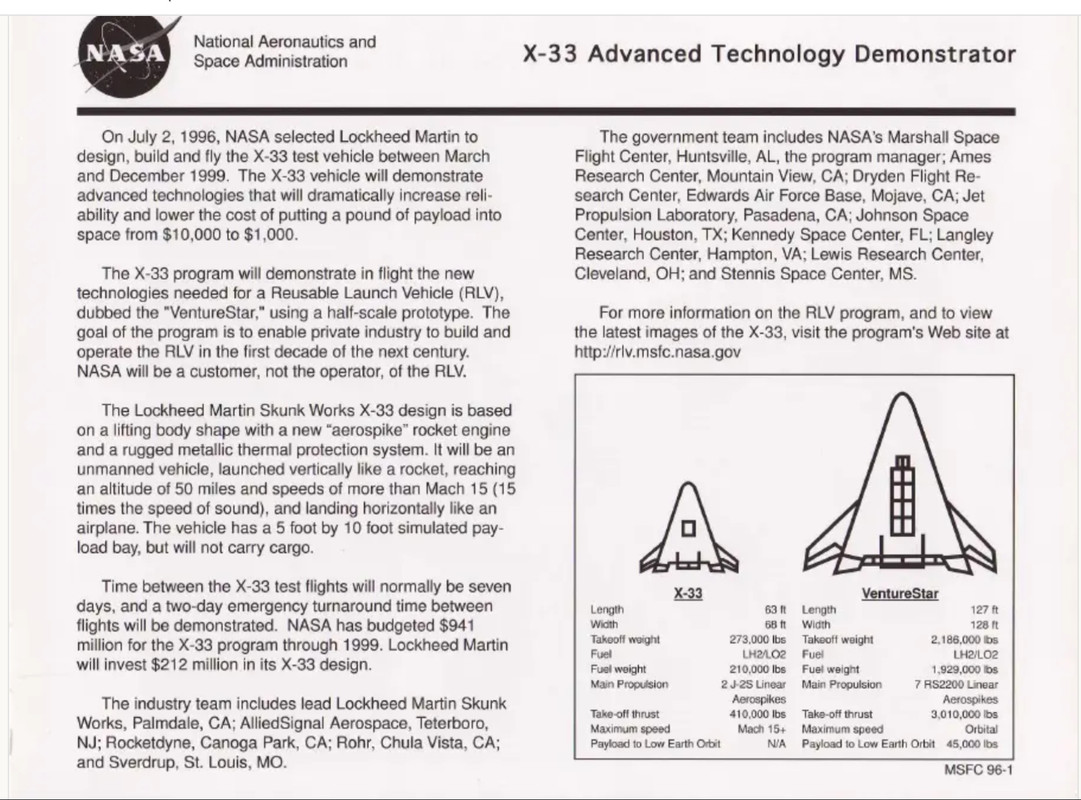
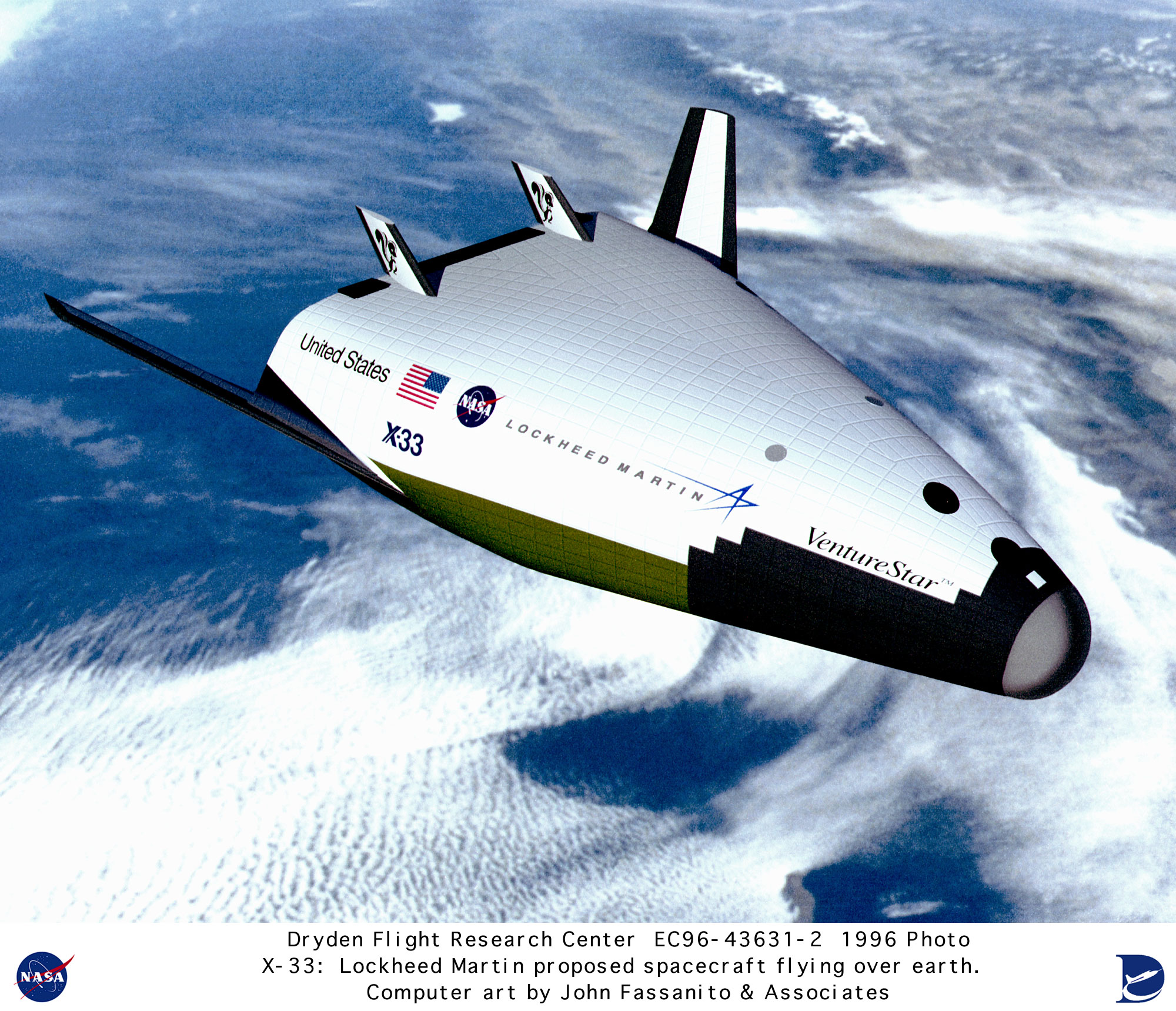
 Then in the following I’ll use the 40 ton value for the Starship dry mass. In this case, there might be an example that would give us a reusable thermal shield for a vehicle the size of Starship. I’m thinking of the X-33/Venturestar.

08287-C50-420-B-4-FDC-A69-B-37-A594-E87808.jpg

 The length in meters was 38.7m and width 39m. For the dry mass, the total gross weight was 2,186,000 lbs, propellant weight 1,929,000 lbs, and payload weight 45,000 lbs; giving a dry weight of 212,000 lbs, or 96,400 kg.

 Using a hypersonic drag coefficient of 2, and considering the triangular planform requires multiplying by 1/2 the length*width to get the area, the ballistic coefficient calculates out to be 96,400/(2*1/2*38.7*39) = 64 kg/sq.m.
 
 Remarkably close to the ballistic coefficient of the Starship at the 60,000 kg mass of the expendable’s dry mass + fairing mass.

 But the added weight of the metallic shingle TPS of the X-33/Venturestar can’t be too high to allow the ballistic coefficient to remain close to this value.
The areal density of the metallic shingle TPS was about 10 kg/sq.m:

REUSABLE METALLIC THERMAL PROTECTION SYSTEMS DEVELOPMENT
Max L. Blosser*, Carl J. Martin*, Kamran Daryabeigi*, Carl C. Poteet **
*NASA Langley Research Center, Hampton, VA, USA
** JIAFS, The George Washington University, Hampton, VA, USA
https://ntrs.nasa.gov/api/citations/200 … 095922.pdf

 The metallic tiles had better resistance to impact and rain than the ceramics at about the same weight.

04-A5-BF90-A019-4278-A5-CC-C3-F33-E7-AFF11.png
Fig.3 Layered metallic sheeting separated by insulation.


09-E4-AEC5-8-B96-424-E-A117-AC5-A11-E2-FC7-E.png

Fig.21 Metallic TPS at same weight of ceramic tiles, ~10kg/sq.m.

At a 10 kg/sq.m. areal density, the added weight covering just the lower half of the Starship would be (1/2)*Pi*9*50*(10 kg/sq.m.) = 7,060 kg, proportionally small enough that the ballistic coefficient would still be ca. 60 kg/sq.m.

This would be advantageous in that you don’t need added wings and you don’t need an additional conical thermal shield.

BUT for this to work SpaceX would have to go back to the smaller, expendable mass of the Starship. SpaceX had tested the X-33 metallic shingles and concluded they were inadequate. But that was with temperatures developed with the higher 160+ ton Starship. With a lighter dry mass, much reduced temperatures result.

Thermal Protection for the Falcon 9 Upper Stage.


 SpaceX had originally intended to make the Falcon 9 upper stage reusable as well as the first stage but decided it was too difficult and chose to only make the first stage reusable. They also engaged in attempts to recover the separated fairing half’s, but decided not to continue implementing this. 

 However, the metallic shingles of the X-33/VentureStar may provide a method to recover the upper stage and fairing.

 This page gives the F9 upper stage as 12.6m long, 3.66m wide at a dry mass of ~4,000 kg, and the fairing as 13.1m long, 5.2m wide, at ~ 1,750 kg:

Falcon 9 FT (Falcon 9 v1.2)
https://web.archive.org/web/20230710234357/https://spaceflight101.com/spacerockets/falcon-9-ft/

 The interstage has been estimated as weighing 1,000kg. Then using again a cylinder’s hypersonic drag coefficient of 2, the ballistic coefficient calculates out to be:

(4,000 + 1,750 + 1,000)/(2*(12.6*3.66 + 13.1*5.2)) = 29.5 kg/sq.m.

 This is well less than the desired 60 kg/sq.m point for metallic shingle TPS. But we have to make sure the added weight of the TPS still allows the ballistic coefficient to stay below this point.

 The weight of this added metallic shingle TPS would be (1/2)*Pi*(12.6*3.66 + 13.1*5.2)*10 kg/sq.m. = 1,800 kg. Adding this on, the ballistic coefficient would still only be 36 kg/sq.m.

 Another possibility though arises from the low ballistic coefficient of 29.5 kg/sq.m from the bare upper stage+fairing without TPS. This is close enough to the 20 kg/sq.m ballistic coefficient point for a stainless steel spacecraft not needing TPS, that should be investigated for the F9 upper stage.

 The tankage, fairing, and interstage would have to be replaced by stainless-steel. The tanks are aluminum-lithium. The specialty high-strength stainless-steel as used on Starship saves about 1/3rd the weight off aluminum-lithium tanks. But the fairing and interstage are composite. The stainless-steel alloys are about the same weight as the carbon-composites.

 Doing some rough estimates it will be approx. at the 20 kg/sq.m point if the tanks and fairing are converted to stainless-steel but the interstage is jettisoned and just use a lightweight steel plate to block the engine from the high temperature air stream during reentry. 


Tuesday, January 15, 2019

SpaceX BFS can be SSTO with altitude compensation.

Copyright 2019 Robert Clark

Rocket equation calculation of payload with altitude compensation.
 In the blog post "SpaceX BFR tanker as an SSTO", I discussed that the tanker version of the BFR upper stage can be SSTO. This is the version of the upper stage without the crew quarters for up to 100 colonists headed for a months long trip to Mars, therefore has a much lighter structural mass.

 However, for the version of the upper stage carrying crew quarters which Elon has called the BFS, for "Starship", Elon has said via twitter it couldn't carry payload as an SSTO:

Elon Musk
Verified account
@elonmusk
Replying to @ludan27 @Erdayastronaut and 3 others
Yes, but single stage to orbit with no payload is pointless. Add Super Heavy rocket booster & orbital payload is gigantic. Only need booster on Earth, due to deep gravity well & thick atmosphere. Starship alone on moons & Mars.
6:00 PM - 22 Dec 2018
https://twitter.com/elonmusk/status/1076613555091234816

 The SpaceX Raptor engine is expected to have quite high chamber pressure, ca. 200 to 300 bar. So the sea level version gets quite good sea level Isp, 330s, and vacuum ISP, 356s. Still the vacuum Raptor gets 382s Isp in vacuum. So I used the rocket equation to estimate the payload under these two vacuum Isp values.

LEO delta-v is 30,000 ft./sec, 9,150 m/s:


 From Modern Engineering for Design of Liquid-Propellant Rocket Engines, p. 12.
https://books.google.com/books?id=TKdIbLX51NQC&pg=PA12&source=gbs_toc_r&cad=4#v=onepage&q&f=false

 The BFR upper stage has 85 ton dry mass, 1,100 propellant mass. Then the sea level Raptor gets barely more than 1 ton to orbit in payload:

356*9.81Ln(1 + 1,100/(85 + 1.3)) = 9,152.6 m/s.

But the vacuum Raptor with 382s vacuum Isp gets nearly 20(!) tons:

382*9.81Ln(1 + 1,100/(85 + 19.8)) = 9,151.2 m/s

 So using alt.comp. on the sea level Raptors so they can launch from ground yet still get the full 382 Isp of the vacuum Raptors would have major advantages as an SSTO. Note that 20 tons payload would be enough for both 100 passengers and their cargo.

The key holdup is that retrofitting usual cylindrical combustion chamber engines to use annular combustion chambers for aerospike nozzles is expensive and time-consuming. Cheaper, faster, and just as effective is to use nozzle extensions. See the J-2X discussion here:

https://web.archive.org/web/20190327061119/http://www.alternatewars.com/BBOW/Space_Engines/J-2X_Airmat_DWG.png

 Remarkable that such a relatively small increase in Isp, results in such a DRASTIC increase in payload, from 1 ton to 20 tons(!) Or said another way, a 7% increase in Isp results in a 1,900% increase in payload! Of course it stems from the exponential nature of the rocket equation.

 I admit I was surprised myself when I did the calculation. We’re familiar with the “tyranny of the rocket equation” for making spaceflight hard. But we forget how beneficial it can be when small, and achievable, increases in Isp result in radical increases in payload. I like to call it the beneficence of the rocket equation.

The Aerospike.
Figure 1: Left: an annularly configured aerospike nozzle. Right: a linear aerospike nozzle. Images courtesy Garvey Spacecraft Corp. & Lockheed Martin Corp.
SIMULATION OF AN OXIDIZER-COOLED HYBRID ROCKET THROAT: METHODOLOGY VALIDATION FOR DESIGN OF A COOLED AEROSPIKE NOZZLE

 I considered the nozzle extension approach to altitude compensation rather than an aerospike since retrofitting an annular combustion chamber for the aerospike to a usual cylindrical combustion chamber engine would be expensive and time consuming.

 However, another approach to an aerospike is to use multiple small engines arrayed around a central spike. This is the approach taken by engineer Philip Bono in his SSTO designs such as the Pegasus and Ithacus in the 60's.

Philip Bono with a model of the Pegasus vehicle [IMG: Douglas Aircraft]
Straight back down to Earth: A history of the Vertical Takeoff/Vertical Landing Rocket – Part 1.

 This was also the approach of the 90's proposed SSTO, the X-33/VentureStar.


 And the approach by the new space start-up Vector Space.


 However, the objection could be made that the large engine bells of the Raptors would not allow enough space for a central spike underneath the stage.

 But for this approach you would cut down the size of the nozzles since some of the expansion would be done by the aerospike. We can estimate the size of the new nozzles.

The NASA page on "Isentropic Flow" has a calculator for calculating the pressure ratio of a rocket, based on the specifications of the engine such as specific heat ratio and area expansion ratio:

 Gamma is specific heat ratio, about 1.2 for LOX/methane. The pressure ratio is the pressure at the nozzle exit to the combustion chamber pressure. Here it's 0.0021, about 1 to 500.  Assuming the combustion chamber pressure for the Raptor is 250 bar, this means the nozzle exit pressure is 1/2 bar.

 We'll cut down the nozzle size, so also the area expansion ratio, so that the exit pressure is actually that of sea level. For the NASA calculator, we'll choose the pressure ratio as one of the inputs, set at 1/250 = 0.004. Then the nozzle area ratio is given as 24 to 1:

 This means the diameter of the shortened nozzle would be smaller by a factor of sqrt(40/24) = 1.29. Since the diameter of the sea level Raptor is 1.3 m, the shortened nozzle would have a diameter of about 1 m. Then the seven sea level Raptors now with 1 m diameter nozzles arranged around the outer portion of the 9 m wide stage base would leave room for a 7 meter wide central aerospike.

 The engines would have their nozzles shortened so that the exit pressure is that of sea level. Commonly with sea level engines, the nozzles are overexpanded so that the exit pressure is actually below sea level. The reason is that sea level engines also have to operate at near vacuum so some intermediate level of expansion is used.

 It might even be better than this. The seven Raptors would have alot of empty space around the aerospike. This likely result in a loss of efficiency. We might want instead to use flattened nozzles so that all together they cover the perimeter of the aerospike, as for instance in the image of the Vector Space aerospike nozzle above.

 This approach may even work for the 31 Raptors under the first stage booster to allow a central aerospike in that case as well.

Aerospike attachment to a standard bell nozzle.
 It might also be possible to give the individual Raptors an aerospike nozzle. One possible way would be by the "double-aerospike"(patent pending):

 This avoids the complexity and expense of converting a cylindrical combustion chamber engine to a toroidal one by attaching this "double-aerospike" to the bottom of the bell nozzle. Since sea level engines are already set up as overexpanded, the internal spike would cut down the exit area so the area expansion ratio would be set to make the nozzle exit pressure be equal to sea level. Then the outer aerospike would perform the usual role of altitude compensation.

 A problem would be heating at the point of the spike, as it is at the point for the usual outward aerospike, but especially so for the inner spike since it will be closer to the combustion chamber temperatures.

 A possible solution would be the ultra high temperature ceramics coming into use in aerospace:

Ceramic matrix composites make inroads in aerospace.
Published on May 14th, 2013 | Edited by: Jim Destefani

Oxide CMC exhaust ground test demonstrator consists of a 1.60-m diameter nozzle and 1.14-m diameter × 2.34-m conical centerbody with titanium end cap inspection portal. Credit: Steyer; IJACT.
https://ceramics.org/ceramic-tech-today/ceramic-matrix-composites-make-inroads-in-aerospace

 It is notable that this jet engine uses an aerospike, or more commonly called plug nozzle for aircraft engines. In fact plug nozzles have been used for decades for jet engines to improve efficiency at high altitude.

 It is therefore puzzling why they have not been adopted for rocket engines. For jet aircraft the cruising altitude night be in the range of 30,000 ft, where the air density would be about 1/3rd that of sea level. Using plug nozzles on aircraft improves payload capacity a few percent. However, for rocket engines on a first stage, they have to operate from sea level to near vacuum. For use as an SSTO, with altitude compensation, the payload can then be improved multiple times.

 Some ultra high temperature ceramics have melting points above 3,900° C. These high temperature materials can also be used in concert with circulating coolant such as with regenerative cooling of rocket engines, as described here:

Ceramic Materials for Reusable Liquid Fueled Rocket Engine Combustion Devices.
Captain Steven Steel
Materials And Manufacturing Directorate
Air Force Research Laboratory
Wright-Patterson AFB, OH
http://rocket-propulsion.info/resources/articles/Ceramic_Materials_For_LPRE.pdf

 Moreover, these ceramic nozzles and engine components can greatly reduce the engine weight:

Sustainable Energy
A More Efficient Jet Engine Is Made from Lighter Parts, Some 3-D Printed.
Composite and 3-D-printed components will mean jet engines that use 15 percent less fuel.
by Kevin Bullis  May 14, 2013
In the LEAP engine, the ceramic matrix composites will replace only some of the nickel alloy parts. But in the future, they could be used for more engine parts, further reducing losses from cooling. This change could also allow engines to run at higher temperatures, making it possible to get more thrust from a given amount of fuel. Furthermore, composites could make engines lighter—parts made from these materials weigh one-third as much as the equivalent nickel alloy parts.
https://www.technologyreview.com/s/514656/a-more-efficient-jet-engine-is-made-from-lighter-parts-some-3-d-printed/

Improvement in lift-off thrust using altitude compensation. 
 Altitude compensation is most known for its ability to allow sea level engines to have higher Isp and thrust under vacuum and near vacuum conditions. However, it is notable it can also allow improved Isp and thrust at sea level.

 The reason is, as mentioned before, sea level engines are commonly overexpanded to improve their performance in vacuum. This however reduces their performance at sea level. This reduction is quantified by the formula:

F = q × Ve + (Pe - Pa) × Ae
where F = Thrust
q = Propellant mass flow rate
Ve = Velocity of exhaust gases
Pe = Pressure at nozzle exit
Pa = Ambient pressure
Ae = Area of nozzle exit
http://www.braeunig.us/space/sup1.htm

 We estimated above using the NASA online calculator the exit pressure of the usual sea level Raptor as 1/2 bar, 50,000 Pascals(Pa). The diameter is 1.3 m for the sea level Raptor. Then the thrust loss at sea level is (50,000-100,000) × π × (1.3/2)2  = 66,400 N, 6,760 kilogram-force, about 4% of the sea level thrust of 1,700 kN.

 Or said another way, using an altitude compensating nozzle can increase the sea level thrust 4%. As the altitude increases, the difference will reduce until the rocket reaches the current nozzles designed set altitude. However, thereafter the improvement in thrust and ISP will again increase until it reaches the max 7% vacuum improvement.


  Bob Clark


Tuesday, July 10, 2018

DARPA's Spaceplane: an X-33 version, Page 3.

Copyright 2018 Robert Clark

 In the previous post "DARPA's Spaceplane: an X-33 version, Page 2"I discussed some recent high strength metal alloys that might give the X-33 and VentureStar even lighter weight propellant tanks than originally envisioned. Still, because of the conformal, noncylindrical shape of the tanks, they would still not have the weight efficiency of a cylindrically shaped rocket. Then I'll discuss some methods that will come close to having the weight efficiency of cylindrical tanks.

Multi-tubed Propellant Tanks.
 One possibility would be to achieve the same lightweight tanks as cylindrical ones by using multiple, small diameter, cylindrical tubes. 

 A similar idea is described here:

OCTOBER 1, 2009 | MECHANICAL & FLUID SYSTEMS
Assemblies of Conformal Tanks
Space is utilized efficiently and sloshing is reduced.
This Prototype Assembly of Conformal Tanks was built to demonstrate the feasibility of building such an assembly to fit an approximately toroidal available volume.
https://www.techbriefs.com/component/content/article/tb/techbriefs/mechanics-and-machinery/5780

 You could get the same volume by using varying lengths and diameters of the multiple cylinders to fill up the volume taken up by the tanks. The cylinders would not have to be especially small. In fact they could be at centimeter to millimeter diameters, so would be of commonly used sizes for tubes and pipes.

 The weight of the tanks could be brought down to the usual 35 to 1 ratio for aluminum-lithium hydrogen/oxygen propellant to tank mass. Then the mass of the tanks on the X-33 would be 210,000 lbs/35 = 6,000 lbs, saving 9,200 lbs off the vehicle dry weight. This would allow the hydrogen-fueled X-33 to achieve its originally desired Mach 15 maximum velocity.

 But note that since now the tanks are composed of cylindrically-shaped tubes, we no longer have the problem of the conformally-shaped carbon composite tanks failing. Then we could get in the range of 50 to 1 propellant to tank mass ratio by using carbon composites for the cylindrically-shaped tubes, and we could reduce the dry mass due to the tanks by an additional 2,000 lbs.

 The same multi-tube approach applied to the full-scale VentureStar would allow it to significantly increase its payload carrying capacity. At a 35 to 1 aluminum-lithium ratio of propellant mass to tank mass for cylindrical tanks, the 1,929,000 lbs propellant mass would now require a mass of only 1,929,000/35 = 55,000 lbs for the tanks, a saving of 83,000 lbs off the original tank mass. This could go to extra payload, so from 45,000 lbs max payload to 128,000 lbs max payload.

 But again we could now use carbon-composites for the cylindrical tubes. This would shave an additional 16,000 lbs off the weight of the tanks, and increase the payload now to 144,000 lbs.

 An analogous possibility might be to use a honeycombed structure for the entire internal makeup of the tank. The X-33's carbon composite tank was to have a honeycombed structure for the skin alone. Using a honeycomb structure throughout the interior might result in a lighter tank in the same way as does multiple cylinders throughout the interior.

 For the multi-tube approach and the honeycombed variant there would be a significant problem for maintenance however. As this is intended to be reusable, we would have difficulty examining all the interior parts of the tanks for cracks or punctures. 

 If you removed the many layers of the multi-tube method layer by layer for examination that would involve significant time and expense. Even more importantly by so many times having to physically move one of the layers of tubes you run an increased risk of damaging one of the tubes. 

 One possibility is that since there would be a gap space between one tube and a tube positioned diagonally to it, we could use this space to insert high resolution imaging equipment. It might also work to insert x-ray imaging devices.

Partitioned Propellant Tanks to Save Weight.
  A different approach to getting near cylindrical-tube weight efficiency, might be to model the tanks, viewing them vertically, as conical but with a flat front and back, and rounded sides. Then the problem with the front and back naturally trying to balloon out to a circular cross section might be solved by having supporting flat panels at regular intervals within the interior. 

 The X-33 composite tanks did have support arches to help prevent the tanks from ballooning but these only went partially the way through into the interior. You might get stronger a result by having these panels go all the way through to the other side.
These would partition the tanks into portions. This could still work if you had separate fuel lines, pressurizing gas lines, etc. for each of these partitions and each got used in turn sequentially. A preliminary calculation based on the deflection of flat plates under pressure shows with the tank made of standard aluminum alloy and allowing deflection of the flat front and back to be only of millimeters that the support panels might add only 10% to 20% to the weight of the tanks, while getting similar propellant mass to tank mass ratio as cylindrical tank. 

 Note you might not need to have a partitioned tank, with separate fuel lines, etc., if the panels had openings to allow the fuel to pass through. These would look analogous to the wing ribs in aircraft wings that allow fuel to pass through. You might have the panels be in a honeycomb form for high strength at lightweight that still allowed the fuel to flow through the tank. Or you might have separate beams with a spaces between them instead of solid panels that allowed the fuel to pass through between the beams

 We'll view the X-33 hydrogen tanks standing vertically as conical with flattened front and back and rounded sides. This report on page 19 by the PDF file page numbering gives the dimensions of the X-33 hydrogen tanks as 28.5 feet long, 20 feet wide and 14 feet high:

Final Report of the X-33 Liquid Hydrogen Tank Test Investigation Team.
https://web.archive.org/web/20120127103443/http://alpha.tamu.edu/public/jae/misc/tankreport.pdf

 Call it 9 meters long, 6 meters wide, and 4.3 meters deep for this calculation. I'll simplify the calculation by approximating the shape as rectangular, i.e., uniformly 6 meters wide. Note that the rounded portions of the sides, top, and bottom will be considered separately. I'll call the vertical length of each section x, and the bulkhead thickness h. Since the length of the tank is 9m, the number of sections is 9/x.


 Typically propellant tanks are pressurized in the 20-40 psi range. I'll take it as 30 psi; call it 2 bar, 2x10^5 Pa. Referring to the drawing of the tank, each bulkhead takes part in supporting the internal pressure of the two sections on either side of it. This means for each section the internal pressure is supported by one-half of each bulkhead on either side of it, which is equivalent to saying each bulkhead supports the internal pressure of one section.

 The force on each section is the cross-sectional area times the internal pressure, so 6m*x*(2*10^5 Pa), with x as in the diagram the vertical length of each section. The bulkhead cross-sectional area is 6m*h, with h the thickness of the bulkheads. Then the pressure the bulkheads have to withstand is 6m*x*(2*10^5 Pa)/6m*h = (2*10^5 Pa)*x/h.

 The volume of each bulkhead is 6m*h*4.3m. The density of aluminum-lithium alloy is somewhat less than aluminum, call it 2,600 kg/m^3. So the mass of each bulkhead is (2,600 kg/m^3)*6m*h*4.3m = 67,080*h. Then the total mass of all the 9/x bulkheads is (9/x)*67080*h = 603,720*(h/x).

 Note that additionally to the horizontal bulkheads shown there will be vertical bulkheads on the sides. These will have less than 1/10 the mass of the horizontal bulkheads because the length of each section x will be small compared to the width of 6m, and will have likewise small contribution to the support of the internal pressure.

 The tensile strength of some high strength aluminum-lithium alloys can reach 700 MPa, 7*10^8 Pa. Then the pressure the bulkheads are subjected to has to be less than or equal to this: (2*10^5 Pa)*x/h <= 7*10^8 Pa, so x/h <= 3,500, and h/x => 1/3,500. Therefore the total mass of the bulkheads = 603,720*(h/x) => 172.5 kg. Note we have not said yet how thick the bulkheads have to be only that their total mass is at or above 172.5 kg, for one of the twin rear tanks. It's twin would also require 172.5 kg in bulkhead mass. The third, forward, tank had about 2/3rds the volume of these twin rear tanks so I'll estimate the bulkhead mass it will require as 2/3rds of 172.5 kg, 115 kg. Then the total bulkhead mass would be 460 kg, about 15% of the 3,070 kg tank mass I calculated for the reconfigured X-33.

 This is for the bulkheads resisting the outwards pressure of the sections. Notice I did not calculate the pressure inside the tank on the bulkheads from the propellant on either side. This is because the pressure will be equalized on either side of the bulkheads. However, we will have to be concerned about the pressure on the rounded right and left sides of the tank, and the rounded top and bottom of the tank, where the pressure is not equalized on the outside of the tank.

 Before we get to that, remember the purpose of partitioning the tank was to minimize the bowing out of the front and back sides from the internal pressure. Consider this page then that calculates the deflection of a flat plat under a uniform load:

eFunda: Plate Calculator -- Clamped rectangular plate with uniformly distributed loading.
This calculator computes the maximum displacement and stress of a clamped (fixed) rectangular plate under a uniformly distributed load.
http://www.efunda.com/formulae/solid_mechanics/plates/calculators/CCCC_PUniform.cfm

 In the data input boxes, we'll put 200 kPa for the uniform load, 6 meters for the horizontal distance, .3 m, say, for the vertical distance, and 6 mm for the thickness of the plate. For the vertical distance x I'm taking a value proportionally small compared to the tank width, but which won't result in an inordinate number of partitioned sections of the tank. For the thickness I'm taking a value at 1/1000th the width of the tank, which is common for cylindrical tanks. For the material specifications for aluminum-lithium we can take the Young's modulus as 90 GPa. Then the calculator gives the deflection as only 2.35mm, probably adequate.

 However, we still have to consider what happens to the rounded sides and the bottom and top. Look at the last figure on this page:


Thin-Walled Pressure Vessels.

http://www.efunda.com/formulae/solid_mechanics/mat_mechanics/pressure_vessel.cfm

 It shows the calculation for the hoop stress of a cylindrical pressure vessel. The calculation given is 2*s*t*dx = p*2*r*dx, using s for the hoop stress. This implies, s = p*r/t, or equivalently t = p*r/s. So for a given material strength s, the thickness will depend only on the radius and internal pressure.

 However, what's key here is the same argument will apply in the figure if one of the sides shown is flat, instead of curved. Therefore in our scenario, the rounded sides, top and bottom, which we regard as half-cylinders, will only need the thickness corresponding to a cylinder of their same diameter, i.e., one of a diameter of 4.3m. 

 So the rounded portions actually require a smaller thickness than what would be needed for a cylinder of diameter of the full 6m width of the tank.

 This means the partitioned tank requires material of somewhat less mass than a cylindrical tank of dimension the full width of the tank plus about 15% of that mass as bulkheads.

 The new high strength metal alloys might also save further on this weight. However, we now have to consider the Young's modulus of the alloys, because of the deflection of the plates calculation, and not just the tensile strength.

A Key Advantage of Partitioned Tanks.
 There is an another advantage of using partitioned tanks in addition to the weight savings. A problem with weight growth of the X-33/VentureStar arose in regards to the size of the wings. For stability reasons, you would want the center of gravity (CG) to remain ahead of the center of pressure (CP) during the entire flight. But as the propellant is burned off, the propellant mass near the front will be decreased and this will increase the effect of the heavy engines at the rear on the moving the CG rearward. To deal with this problem during the X-33 development, the wings kept getting larger and larger. But this cancels out the advantage the X-33 had in its dry mass in its original design in not needing heavy wings.

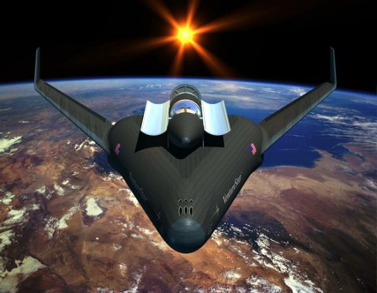
 The original X-33/VentureStar was supposed to look like this:


 But in the later incarnations, it looked like this:


 The added wing size was to move the CP rearward to keep the CG ahead of it. 

 Partitioned propellant tanks are nothing new actually in aerospace. They are quite commonly used on jet airliners to deal with the problem of CG shift as fuel is burned off:

Concorde.
Balancing by Fuel-Pumping.
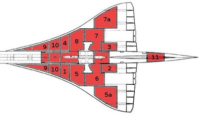
The Concorde Tank-Schematic:

"1 + 2 + 3 + 4 are the Collector-Tanks, feeding the engines directly. Usually they feed there counterpart engines – but they can be cross-switched to feed more and/or other engines at the same time.
5 + 7 and 8 + 6 are the Main-Transfer Tanks, feeding the 4 Collector-Tanks. Initially 5 + 7 are active. If those are empty 6 + 8 take over (or must be activated from the Engineering Panel!).
5a + 7a are Auxiliary-Tanks (to 5 and 7).
9 + 10 are the Trim-Tanks for balancing forward
11 is the Trim-Tank for balancing afterward"

 Then the partitioned tanks could solve two problems of the dry mass of the X-33/VentureStar: weight growth in the tanks and in the wings.


 Bob Clark

Sunday, June 10, 2018

DARPA's Spaceplane: an X-33 version, Page 2.

Copyright 2018 Robert Clark

 The OldSpace companies had always discounted the viability of reusable launchers on the grounds that the launch market was not enough to pay for it. However, a new market will soon be opening up for hundreds to thousands of launches required for the impending satellite megaconstellations. Now even the OldSpace company ArianeSpace is speaking of transitioning to reusability.

 So with reusability soon to become prevalent we have now further justification for resurrecting the X-33. Boeing supported by a DARPA grant is developing a reusable, spaceplane first stage, the XS-1, then Lockheed with the X-33 would have a competing reusable launcher.

 In the blog post DARPA's Spaceplane:an X-33 version, I discussed that the X-33 used as a reusable first stage has importance beyond that of just a test stage of an operational SSTO, the VentureStar. For the X-33 could be its own operational vehicle, cutting costs in its own right as a reusable first stage.  But intriguingly the problems that originally doomed the X-33 and its SSTO follow-on the VentureStar may also be solvable.

 As discussed in that earlier post, it was the failure of the composite tanks that caused the X-33 program to be cancelled. But some new high strength aluminum alloys may have the comparable lightweight characteristics as carbon composite tanks.

 Carbon composite propellant tanks are a pretty well developed technology, as long as they are cylindrically shaped. But the unusual conformal shape of the composite tanks on the X-33 caused them to fail.

 Carbon composite saves about half-off the weight of standard aluminum tanks. But interestingly some new aluminum alloys have comparable high strength at lightweight as carbon composite and therefore could be used to give the lightweight tanks needed. 

 See for example the graphic:


  The 7075 T6 alloy has nearly twice the strength per weight as the standard 6061 T6 alloy, and the 7068 T6 was nearly 2.5 times better. 

 A consideration as described on that page is that 7075 is 2 to 3 times more expensive than the standard 6061 and the 7068 is 3 to 4 times more expensive. But considering that because of their higher strength, smaller amounts of the material by a factor of 2 to 2.5 would be needed the price difference in practice would not be as great.

 Note also since it was the inability to produce the composite tanks in the X-33 at the needed lightweight that caused the program to be cancelled, existence of the high strength aluminum alloys make the SSTO VentureStar once again viable.

 Development Cost.

 The cost of carbon fiber is about twice that of standard aluminum, so the cost of the tanks with high strength aluminum would not be much more than the cost of the carbon fiber X-33. Since Lockheed would be paying this itself, it might want first to do a smaller version of the X-33.

 In the earlier "DARPA's SpacePlane" post, I suggested a smaller version half-size in linear dimensions of the X-33 might cost ca. $45 million to build. This would test the technology and moreover using it as an upper stage of the X-33 would give a fully reusable system.

   Bob Clark

UPDATE 7/4/2018: 

 I've been informed of other other high strength, lightweight metal alloys that could also allow VentureStar to achieve its goal of a being a reusable SSTO, and allow the X-33 to be able to serve as a low cost reusable first stage.

 The alloys have various strengths and weaknesses. For example some are are just now being experimented with but their measured strength-to-weight ratio is more than 3 times better than standard aluminum. Some are steel alloys which have better weldability than the aluminum alloys, etc.

 For instance in the graphic above, the titanium 6Al-4V alloy is a little better than the 7075 and is already used in rockets for example for solid motor casings.

 There is also a high strength steel alloy, the 17-7 PH stainless steel CH 900:

Re: SpaceX second stage secret sauce?
https://forum.nasaspaceflight.com/index.php?topic=41906.msg1626634#msg1626634

 It has comparable strength-to-weight as the 7068, i.e., nearly 2.5 times better than standard aluminum. It also has better weldability than the aluminum alloys.

 A recent report shows some high strength aluminum alloys such as the 7075 can be 3D-printed:

Engineers Have Found a Way to 3D Print Super Strong Aluminum.
B. Ferguson/HRL Laboratories
by Dom Galeon September 22, 2017 Hard Science
https://futurism.com/engineers-have-found-a-way-to-3d-print-super-strong-aluminum/

 This is useful since the high strength aluminum alloys such as the 7075 have poor weldability. But the conformal shapes of the X-33/VentureStar tanks would be difficult to make without welding.

 Ti 5553 alloy is another ultra strong titanium alloy, even better than the Ti 6Al-4V. It has a max tensile strength in the range of 1,400 MPa. At a density of 4.64 gm/cc, this puts it in strength-to-weight ratio at even better than the 7068 alloy, and nearly 3 times better than standard aluminum:

Processing of a metastable titanium alloy (Ti-5553) by selective laser melting.
November 2016Ain Shams Engineering Journal 8(3)
https://www.researchgate.net/public...nium_alloy_Ti-5553_by_selective_laser_melting

Finally, a titanium alloy known as the Ti185 was long known but it was difficult to produce it so it had uniform strength throughout. A new method of producing it using titanium hydride powder can produce it so it is uniformly strong:

Low-cost and lightweight: Strongest titanium alloy aims at improving vehicle fuel economy and reducing CO2 emissions
April 1, 2016, Pacific Northwest National Laboratory

https://phys.org/news/2016-04-low-cost-lightweight-strongest-titanium-alloy.html

 Approaching 1,700 MPa in tensile strength, it would be 3.5 times better on strength-to-weight than standard aluminum. Because it is made of titanium hydride powder, it may also be possible to make it by 3D-printing, which would solve the problem of producing a conformal shape for the tanks of the X-33/VentureStar.


Saturday, October 5, 2013

DARPA's Spaceplane: an X-33 version.

Copyright 2013 Robert Clark


 DARPA has announced that it will be funding research into a reusable first stage booster to carry an orbital upper stage. But looking at the specifications of the cancelled programs the DC-X's suborbital follow-on, the DC-X2, and on the X-33 you'll note that they each could have performed this role. This would have led to greatly reduced orbital costs. Then both programs were cancelled prematurely.

 Part of the problem is that they were viewed as purely demonstration or experimental programs, without any potential profitability of their own. The profitability would have come with the full, and expensive, SSTO programs to follow. However, if it had been noted these could have been used as fully reusuable first stages, then their value would have been seen on their own. So that they would have been understood as deserving of funding whether or not the SSTO's were to follow.

 The story of the X-33 is well-known now among space advocates:

X-33/VentureStar – What really happened.
January 4, 2006 by Chris Bergin
http://www.nasaspaceflight.com/2006/01/x-33venturestar-what-really-happened/

 It was to be a suborbital experimental test vehicle for a larger SSTO called the VentureStar. For the VentureStar to have been SSTO with significant payload would have required aggressive weight saving techniques such as composite tanks. Such composite tanks were to be tested on the X-33 before committing to the full VentureStar.

 However, the composite tanks failed on the X-33. Since it was felt the SSTO version could not succeed with regular metal tanks, the program was cancelled. However, in point of fact even if you replaced the failed composite tanks with aluminum-lithium ones the X-33 could still be used as a reusable first stage.

 The problem with the tanks is that their unusual conformal shape required them to use greater tank mass compared to the mass of propellant carried than by usual cylindrically shaped tanks:

Space Access Update #91 2/7/00.
The Last Five Years: NASA Gets Handed The Ball, And Drops It.
...part of L-M X-33's weight growth was the "multi-
lobed" propellant tanks growing considerably heavier than promised.
Neither Rockwell nor McDonnell-Douglas bid these; both used proven
circular-section tanks. X-33's graphite-epoxy "multi-lobed" liquid
hydrogen tanks have ended up over twice as heavy relative to the
weight of propellant carried as the Shuttle's 70's vintage aluminum
circular-section tanks - yet an X-33 tank still split open in test
last fall. Going over to aluminum will make the problem worse; X-
33's aluminum multi-lobed liquid oxygen tank is nearly four times as
heavy relative to the weight of propellant carried as Shuttle's
aluminum circular-section equivalent.
http://www.space-access.org/updates/sau91.html

  However, ironically it turned out that the hydrogen tank weight for the X-33 actually went down when replaced by aluminum:

From "X-33/VentureStar – What really happened" :
Faced with a project failure, Lockheed Martin and X-33 NASA managers gave the green light to proceed with the fabrication of the new tank. Ironically this new tank weighed in less than the composite tank – disproving one of the reasons for going with a composite tank in the first place.
While the aluminium LH2 tank was much heavier than the composite tank in the skins, the joints were much lighter, which was where all the weight in the composite tank was, due to the multi-lobed shape of the tank requiring a large amount of surrounding structure, such as the joints. Ironically, the original design of the X-33 on the drawing board had the tanks made out of aluminium for this reason – but the cost played a factor for the potential customer base.
Then on replacing the composite hydrogen tanks with Al-Li the dry mass should be less. So I'll use the same numbers for the dry mass and gross mass, 75,000 lbs for the dry mass and 285,000 lbs for the gross.

 The X-33 was to use two aerospike XRS-2200 engines. According to Wikipedia, the XRS-2200 produces 204,420 lbf (909,300 N) thrust with an Isp of 339 seconds at sea level, and 266,230 lbf (1,184,300 N) thrust with an Isp of 436.5 seconds in a vacuum. So two will have a vacuum thrust of 2,368,600 N.

 Now choose for the upper stage an efficient cryogenic stage such as the Centaur or the Ariane H10. We'll use Dr. John Schilling's Launch Performance Calculator to estimate the payload possible. Take the specifications for the Centaur rounded off as 2,000 kg dry mass, 21,000 kg propellant mass, 100 kN vacuum thrust and 451 s vacuum Isp. Then the Calculator gives a payload of 5,275 kg to orbit:

Mission Performance:
Launch Vehicle:  User-Defined Launch Vehicle
Launch Site:  Cape Canaveral / KSC
Destination Orbit:  185 x 185 km, 28 deg
Estimated Payload:  5275 kg
95% Confidence Interval:  4252 - 6507 kg

 The cost of a Centaur upper stage is in the range of $30 million. But how much for a reusable X-33? This article gives the cost to build a X-33 as $360 million in 1998 dollars:

Adventure star  
12:00 18 Nov 1998  Source:  Flight.
By:  Graham Warwick/WASHINGTON DC

 Even taking into account inflation the cost should not be terribly much more than that when you also take into account the decrease in price for composites because of their more common use. 

 The launch preparation costs should also be low since the X-33 was expected to be operated by only a 50 man ground crew compared to the 18,000 required for the shuttle system:

Lockheed Secret Projects: Inside the Skunk Works.

 Say the builder expected a 25% profit over cost of the vehicle over 100 flights. That would be a charge of $4.5 million per flight. With the Centaur upper stage that would be $34.5 million per flight for 5,275 kg to orbit, about $6,500 per kilo. This is a significant saving over the ca. $10,000 per kilo for launchers in the West. It is still well above DARPA's desired price point of $5 million per flight, but it is for a larger payload than the DARPA required 3,000 to 5,000 pounds.

 A lower cost launcher could be obtained using a cheaper upper stage, such as the Ariane H10 stage. This is about 12 mT in propellant load and 1.2 mT in dry mass at 445 s vacuum  Isp and 63 kN vacuum thrust. The Calculator gives a payload mass of 3,762 kg.

 The cost for the H10 stage according to Astronautix is $12 million. Then the total would be $16.5 million. At a payload of 3,672 kg, this is $4,500 per kilo. This would be a great cut in cost for small size payloads, but the total cost is still too high for the DARPA price requirements.

 Another possibility for a cheaper upper stage would be the Falcon 1's first stage. This has a dry mass of 1,450 kg and propellant mass of 27,100. We'll use for it though the upgraded Merlin 1D Vacuum at 800 kN vacuum thrust and 340 s Isp. Then the Calculator gives a payload mass of 5,238 kg. 

 The latest listed price for the Falcon 1 in 2008 was about $8 million. But we only need the first stage. Elon Musk has said for the Falcon 9 the cost of the first stage is 3/4ths the cost. If also true for the Falcon 1, that would put the cost at $6 million for the first stage. Then the total cost would be $10.5 million, $2,000 per kilo. This is a quite low cost per kilo and it would be a significant advance to have payload this size launched at such low cost, whether or not it would qualify under the DARPA program.
  
 We can get closer though to the DARPA total cost requirement by taking instead the Falcon 1's upper stage. This has a 360 kg dry mass and 3,385 kg propellant mass. The vacuum thrust is 31 kN and vacuum Isp, 330 s. Then the Calculator gives a payload of 959 kg. Taking the cost of the Falcon 1 upper stage as 1/4th that of the $8 million cost of the Falcon 1, this puts the total cost as $6.5 million

 This is a little below the DARPA requirement to LEO of at least 3,000 lbs and at a cost a bit above the $5 million limit, but likely tweaking the sizes of the lower and upper stages can get them within the required range.

 In regards to changing the size, an ideal solution would be to get an upper stage from a scaled down X-33. This would in fact allow us to get a fully reusable two-stage system. Say we scaled down the size of the X-33 by a half in the linear dimensions. This would give us a vehicle 1/8th as large in mass. Then the dry mass would be 4,000 kg with 12,000 kg propellant mass. Take the thrust as 1/8th as large as well at 300 kN, while using the same Isp 436.5 s. Then the Calculator gives us a payload of 1,902 kg.

 Given its 1/8th as large mass, we may estimate the cost to build this half-scale X-33 as $45 million. Using again a 25% price markup over 100 flights, that would be $560,000 per flight. This then would be quite close to the total cost range requirement for the DARPA program.


   Bob Clark

Thursday, June 21, 2012

Low Cost HLV, page 3: Lightweighting the S-IC Stage.

Copyright 2012 Robert Clark


                                                    SASSTO 
                                                    SASSTO - Saturn-derived SSTO Launch Vehicle 
                                                    Credit: © Mark Wade


 I showed in the post Low Cost HLV, page 2: Comparison to the S-IC Stage that the S-IC first stage of the Saturn V could give a nearly 20-to-1 mass ratio using a lighter thrust structure and using four RD-171 engines instead of five F-1 engines. But in fact we can do better than this. The S-IC of the 1960's did not have available the aluminum-lithium alloy used for example on the Falcon 9 and shuttle ET. Here I calculate a lighter structure using this lighter alloy and some mass reducing structural changes.

 The tank mass of the S-IC stage and of some other rocket stages is discussed in this key report:

Single Stage To Orbit Mass Budgets Derived From Propellant Density and Specific Impulse.
John C. Whitehead
32nd AIAA/ASME/SAE/ASEE Joint Propulsion ConferenceLake Buena Vista, FLJuly 1-3, 1996
http://www.osti.gov/bridge/servlets/purl/379977-2LwFyZ/webviewable/379977.pdf

 On page 8 in Fig. 6 is given a comparison of the tank weights of the Saturn S-IC, Atlas II, and shuttle ET:


 We've already reduced the mass of the stage down to 113,000 kg by using a lighter thrust structure in the prior post. Fins are not really needed for large rockets with computer guidance and control, so remove these to reduce the mass again to 112,000 kg. The  four 4 meter diameter RD-171 engines can fit under the 10 meter diameter S-IC tank, so remove the engine fairings to bring the mass down to 108,000 kg.
 Now use common bulkhead design to reduce the tank mass further. The question of using common bulkhead design for the S-IC arose during the Apollo design period:

SP-4206 Stages to Saturn.
7. The Lower Stages: S-IC and S-II.
THE S-IC AND THE HUNTSVILLE CONNECTION.
The main configuration of the S-IC had already been established by MSFC, including the decision to use RP-1, as opposed to the LH2 fuel used in the upper stages. Although LH2 promised greater power, some quick figuring indicated that it would not work for the first stage booster.Liquid hydrogen was only one half as dense as kerosene. This density ratio indicated that, for the necessary propellant, an LH2 tank design would require a far larger tank volume than required for RP-1. The size would create unacceptable penalties in tank weight and aerodynamic design. So, RP-1 became the fuel. In addition, because both the fuel and oxidant were relatively dense, engineers chose a separate, rather than integral, container configuration with a common bulkhead. The leading issue prior to the contract awards related to the number of engines the first stage would mount.
http://history.nasa.gov/SP-4206/ch7.htm#197

   This could be interpreted to mean the density of the propellant made it unfeasible, but I think the relatively smaller tankage mass using the dense propellants made the more difficult common bulkhead design unnecessary. For instance as you see in that Fig. 6 from Whitehead's report, in the shuttle ET tank the intertank weighs more than the entire oxygen tank. The relative weight of the intertank is not as bad for the kerosene S-IC. Still, common bulkhead design is used for the large kerosene first stage on the Falcon 9 to help save weight.

 So to minimize stage weight we will remove the interstage and one of the bulkheads. Assuming top and bottom bulkheads weigh the same for each of the LOX and kerosene tanks on the S-IC, then from the information in Fig. 6, the LOX bulkheads weigh 4 mT each and the kerosene, 3.3 mT. Conservatively, let's say we remove one of the kerosene bulkheads instead of a LOX bulkhead since we may need the larger LOX bulkhead for strength. Then also removing the 6 mT intertank, we bring the dry mass down to 99 mT.

 Now estimate the weight saving using the lighter aluminum-lithium alloy. From the Wikipedia page on the shuttle ET, the tank weight reduced from 35,000 kg using aluminum alloy 2219, the same alloy used for the S-IC tanks, to 26,500 kg using aluminum-lithium alloy, a reduction of 24%.

 After the structural changes, the tanks now weigh 25.5 mT. Subtracting off 24% from this is a reduction in mass by 6 mT. This brings the stage mass down to 93 mT.

 Keep in mind though, the plan is to use a shuttle ET size tank to save cost on tooling. The ca. 720 mT hydrolox of the shuttle ET becomes ca. 2,100 mT with the 3 times denser kerolox. This turns out to be about the same kerolox carried by the S-IC. So the purpose here was just to get an idea of a lightweight stage you can get using modern materials.

 Now notice you get significant payload as a SSTO using the RD-171 engines at 338 s vacuum Isp. Taking the required delta-v to orbit as 9,150 m/s for kerolox, you can get 48 mT to orbit:

338*9.81ln(1 + 2,100/(93 + 48)) = 9,170 m/s.

 Note though that if we are to use the shuttle ET as a stage then the pointed end of the LOX tank would need to be removed. We could take the equivalent cylindrical LOX tank of the same volume. It would have the same dry weight, so the stage dry mass stays the same.

 However, if you take the full length of a cylindrical tank now as 46.9 m and the diameter as 8.4 m, per the specifications of the SLWT version of the ET, and the density of kerolox as about 1,030 kg/m^3, then we get about 2,600 mT kerolox. The tank weight would increase somewhat without the pointed end, but not by much compared to the entire stage weight. Then you could loft 82 mT to orbit:

338*9.81ln(1 + 2,600/(93 + 82)) = 9,160 m/s.

 A propellant load of 2,600 mT at dry mass of 93 mT corresponds to a mass ratio close to 29 to 1, rather high. But SpaceX has said with their side boosters on the Falcon Heavy they expect to achieve a mass ratio of 30 to 1, and mass ratio does get better as you scale up a stage,with this shuttle ET size stage being much larger.

 This payload of 82 mT is better than the 70 mT to be carried by the interim SLS. Remember our HLV is to be developed using the SpaceX-style commercial approach. Then based on a $2,000/kg price of the Falcon Heavy, the full two stage version of our HLV as comparably priced might only cost ca. $200 million per launch at a 100 mT payload to orbit.

 So the SSTO version would even cost less than this, perhaps only ca. $100 million per launch for the 82 mT payload to orbit.

 The dry weight could be lightened further by using composites. Estimates put the weight savings in the structural mass in the 40% range for a fully composite structure. In that case the payload could exceed 100 mT for this SSTO.

 An increase of the Isp could be possible by using an aerospike or plug nozzle, up to the range of 360 s. The multi-nozzle format of the RD-171 engines makes this feasible. The four nozzles of each engine would be shortened and arranged around a central aerospike. This was the idea behind the aerospikes planned for the X-33 and VentureStar. It was also used earlier in the planned Beta SSTO of Dietrich Koelle and the SASSTO SSTO of Phillip Bono.

 An argument against this was that the aerospike nozzle would make the propulsion system too heavy. For instance for the aerospike on the X-33 the thrust/weight ratio was only 40 to 1, compared to a 70 to 1 ratio for the SSME's for example. However, the lightweight, high temperature ceramics and composites available now should make the T/W comparable to bell nozzle engines:

Ceramic Materials for Reusable Liquid Fueled Rocket Engine Combustion Devices.
http://ammtiac.alionscience.com/pdf/AMPQ8_1ART06.pdf


  Bob Clark

Note: The SASSTO SSTO shown at the top and discussed near the end was derived from the Saturn S-IVB stage, not the S-IC, and was hydrogen fueled. The Beta SSTO discussed was also hydrogen fueled. However, a key result of the cited report of John C. Whitehead is that it is actually easier to make a kerosene-fueled SSTO. This is because the large and heavy hydrogen fuel tanks swamps out the advantage of its higher Isp.  - B.C., 6/22/2012.

Could Blue Origin develop a lander for Artemis III?

Copyright 2025 Robert Clark SpaceX is coming under increasing criticism for its delay in developing the Starship lunar lander: U.S. Is Losin...