In a recent discussion of the BFR, Elon Musk has discussed giving the BFS upper/landing stage extended-size fins, to the extent they resembled wings, to help with the landing on Mars:
Elon Musk reveals updated design for future SpaceX Mars rocket.
By Loren Grush@lorengrush Sep 17, 2018, 9:38pm EDT
In fact in this video Musk alternately called them wings and fins:
Primarily these would be for control during reentry on Mars. The final landing would be through a propulsive, vertical landing.
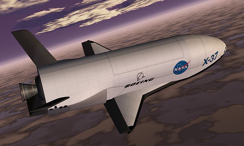
The idea has been that full wings would be too heavy, as for the Space Shuttle for example. However the X-37 provides an example that shows a reentry stage can use short, stubby, and therefore lightweight wings, to do a full horizontal landing on Earth:
Boeing has not given the breakdown of the masses of the structural components of the X-37. But the Skylon gives another example of an orbital stage doing a fully, horizontal landing with short stubby wings:
The designers of the Skylon have given the weight of the carbon fiber wings as only 2% of the gross takeoff weight. Because the Skylon does a horizontal takeoff, the wings have to support the full gross takeoff weight. But for the BFS assuming it flies a non-lifting trajectory to orbit, the wings would only have to support the dry(empty) weight for when it returns from orbit. This would mean a much smaller weight for the wings.
For example, if we applied this to the Falcon 9 upper stage, the gross takeoff mass is about 100 metric tons, but the dry weight only about 4 metric tons. The 2% of the dry mass would only be about 80 kg for the wings.
It may even be possible to get even smaller weight for the wings. A remarkable new development is lightweight but strong materials is the isotruss:
From the graph it is nearly twice as good as carbon fiber in bending strength on a per weight basis. So a Skylon-type wing might only have to be 1% of the landed weight or only 40 kg for the Falcon 9 upper stage.
Such small-size wings still would not provide a fully horizontal landing in the thin atmosphere of Mars, but they would cut down the amount of propellant needed for the propulsive landing.
Bob Clark
UPDATE, 12/15/2018:
The latest update on the SpaceX BFR is they intend to use metals for the tanks and other structures:
Then SpaceX succeeding in this could give impetus to resurrecting the X-33/Venturestar with high strength metal structures rather than carbon composite.
Additionally, I suggested above using the isotruss for its bending strength for the structures such as wings. It is notable that the isotruss obtains its strength from its unique geometry since while it is composed of carbon composite it is twice as strong as a standard carbon composite tube.
Isotruss Tower
280' tower installed in Spanish Fork, Utah
This suggests that a metal isotruss also could be twice as strong as a standard metal tube, and should therefore be even stronger when made of the specialty high strength metals SpaceX is considering.
Another intriguing possibility is suggested by this. A recent development is scifer steel wire:
Like carbon fiber this is only available in wire form, not sheets. However, it has from two to three times greater strength than the high strength steels available in sheet form. So the scifer wire could still be used to form a steel isotruss, possibly doubling its bending strength.
Then I'll propose an alternative solution to achieving the long-distance water flow. In the high volume, high head "mud pumps" discussed in the Page 2 blog post, the pumps necessarily had to have both high volume and high head because in their dredging, mining, drilling use they have to pump both mud and rocks in addition to just water.
The problem with sending water streams long distance is that the water streams will disperse into droplets due to air drag under the high speeds or pressures needed to send them the long distances. However, rocks certainly can be sent such long distances even acting under air drag. So the idea would be to have the water contained as some percentage within mud or rock. Depending on the relative proportion of the mud/rock to the water, the individual packets would be sufficiently cohesive to be sent the required distance.
Another possibility would be to send the water as frozen blocks or balls. There would be the question then of how to get the water rapidly frozen while being sent out at high pressure or speed. One possibility would be to first use snow making machines that can make snow using up to 107 gallons per minute of water. The water is sent out in the form of a fine mist so that it will rapidly freeze. You would also need a compartment of refrigerated air kept below freezing so that the water will rapidly freeze like in the Winter conditions on a ski slope:
The snow is made in the form of small ice crystals though. The snow/ice would then have to be compressed into balls or cubes so it would have longer range when then sent to the high pressure pumps.
Still another possibility is the water could be encased in a biodegradable plastic bag or shell before being sent to the high pressure pumps.
To minimize drag we might want to put the encased or frozen water into a tear drop shape. We might also want to give it fins and use spin stabilization for a straight-line flight kilometers long.
A gliding approach to long range.
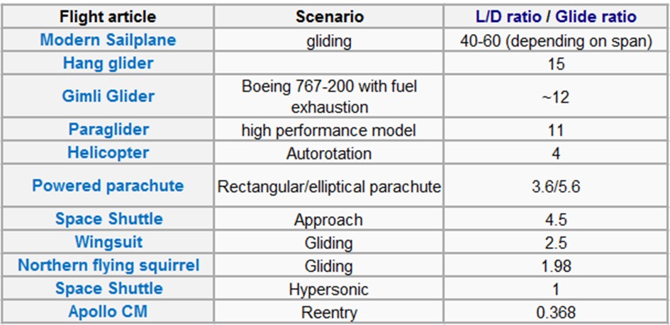
To get even longer range, we could also shape the mud packs, ice packets, or plastic shells into aerodynamic lifting surfaces. Gliders for example can have lift/drag ratios in the range of 40 to 60.
The glide ratio which is the ratio of the horizontal length traveled divided by the vertical drop is equal to the lift/drag ratio.
Then encasing the water into a gliding aerodynamic shape with a ca. 60 to 1 lift drag ratio, we could cover 24,000 feet horizontally as it fell 400 feet.
This would have the advantage in that you would not need to convert this high volume pumping capacity into lower volume, but higher head.
The disadvantage is the high lift/drag ratio shape of a sailplane would be highly subjected to winds.
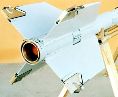
So we likely would need some method of automated control surface maneuvering to ensure straight and true flight. One possibility might be the rolleron fins used on rockets:
A rolleron is a type of aileron used for rockets, placed at the trailing end of each fin, and used for passive stabilization against rotation.[1] Inherent to the rolleron is a metal wheel with notches along the circumference. On one side, the notches protrude into the airflow. During flight, this will spin the wheels up to a substantial speed. The wheels then act as gyroscopes. Any tendency of the rocket to rotate around its major axis will be counteracted by the rollerons: the gyroscopic precession acts to move the rolleron in the opposite direction to the rotation.[2]
Studies on the flow distance of non-laminar water streams show their distance is dependent on where the break-up distance occurs, [1]. This is known to be dependent of turbulence within the piping. Laminar flow achieves longer distance because of reduced turbulence. Then the natural question to ask is how much we can reduce turbulence.
Certainly, a rough surface within a pipe induces high turbulences. Then the best we could do to reduce that is to use an atomically flat surface. A report shows at least in helium gases shows atomically flat surfaces can reduce drag by orders of magnitude:
Gas flow through tiny atomically flat walls: Atomic-scale ping-pong.
Date: June 20, 2018
Source: University of Manchester Published in Nature, this new research shows that the channels allow gas through them at rates that are orders of magnitude faster than expected from theory. This will not only be important for fundamental studies on molecular flows at nanoscale but also for applications such as desalination and filtration. The reported anomalously-high flow is due to a phenomenon called 'specular surface scattering', which allows a gas to pass through the channel as if it were not there at all. https://www.sciencedaily.com/releases/2018/06/180620150200.htm
Note this would be important not just for inducing low turbulence and laminar flow for a pipe-free approach but also for the approach using piping to reduce drag and pressure loss.
Actually, there are two effects involved in this report that need to be investigated separately. One, is that the surface is atomically flat, the other is that the channels are at nanoscopic widths.
The flatness at atomic scales would likely reduce drag and turbulence for macroscale pipes, and therefore also improve the laminar flow effect on exiting the pipe.
But an aspect of how laminar flow streams are produced suggests the nanoscale piping in itself would also improve laminar flow. In the case of laminar flows in amateur experimenters, they were produced by using multiple small straws placed within the pipe to produce multiple small streams. The experimenters noted the effect is much better for small straws as for example coffee stirrers compared to larger straws as used for example sodas. Then the natural question that needs to be investigated is how much better would the effect be for microscale and nanoscale piping.
In extending the results of the published report on helium gases to water another effect needs to be taken into account, the stickiness of water on surfaces. Materials low in this measure are called hydrophobic. Recent research has been on materials extremely low on this measure called superhydrophobic. In this case simulations and experiments show the drag can be reduced 50%, [2].
(I.)Introduction.
Stonehenge has been a mystery for a long time. How did these pre-technology peoples, in the time range of 3,000 to 2,000 BC, raise these huge stones weighing several tons?
A recent theory gaining credence is that they let gravity do the work. The stones actually extend down into the ground. The theory for how they were raised was that they dug a pit under the horizontal stones extending from about a third of the way from one edge. The stones were constructed thicker and so heavier at this edge. Then gravity would cause that end to fall into the pit. This part would then be covered up letting the remaining part be visible above ground.
See for example these videos explaining the theory:
How Stonehenge site was built.
AMAZING VIDEO: Man Lifts 20 Ton Block By Hand.
So rather than the many concerns about building the high altitude towers vertically, instead they would be built horizontally, and we would then follow the Stonehenge builders by allowing gravity to raise them vertically.
For a space tower that might be up to 100 km high however, we would need a deep pit for the one end to fall into, likely kilometers deep. For the purpose, we'll use the deep depths of the ocean. The ocean basins can be in the range of 5 km deep.
We will then put a heavy weight on one end to cause the rest of the tower to rise vertically.
How much will the tower weigh and much will we have to use as a weight on the bottom to raise it? This article gives the formulas for the weight and taper ratio of a tower based on height and materials used.
In section 3 are given formulas for the taper of the tower and for the tower mass. The formulas are complicated for the general case where you have to consider the variation of gravity with altitude and centrifugal forces when the tower or elevator may extend thousands of kilometers into space. However, for the shorter case of less than 100 km, it reduces to being exponential in the ratio of the height to the characteristic length.
The characteristic length is the maximal length of a straight, untapered, column of the material that can support its own weight. It is given by Lc = σ/(ρ*g), σ, the compressive strength of the material, ρ is the density and g, the gravitational acceleration at the surface. Usually, you want the tower to be tapered to minimize mass even if it is less than the characteristic length. If it is larger than the characteristic length then it will necessarily have to be tapered..
The formula for the taper is, A = A0*exp[-L/Lc], where A is the area at the top of the tower, A0 is the area of the base, and L the length of the tower. And the formula for the tower mass is, M = M0*(exp[L/Lc] - 1).
Various grades of steel have varying strengths. An especially strong, and expensive, grade is 350 Maraging Steel at a 2,400 MPa compressive strength, and 8,200 kg/m3 density, for a characteristic length of 29.8 km.
There are some composite materials with better strength-to-weight ratios. See for example here:
These tables are for reference / information only and are NOT a guarantee of performance
1 GPa = 1000 MPa = 1000 N/mm² = 145,000 PSI
These tables relate to only 2 of the many fibre orientations possible. Most components are made using combinations of the above materials and with the fibre orientations being dictated by the performance requirements of the product. Performance Composites Ltd. can assist with the design of components where appropriate.
The standard carbon fiber fabric has a compressive strength of 570 MPa at a density of 1.60 g/cc, 1,600 kg/m3, for a characteristic length of 36.3 km. This is the type of fabric that has the fibers aligned in multiple directions.
Unidirectional composites (UD) however have greater strength in the direction of the fibers, and markedly reduced strength outside of that direction. The carbon fiber unidirectional composite (CF UD) has a compressive strength of 1,200 MPa at a density of 1,600 kg/m3, for a characteristic length of 76.5 km, but only in the direction of the fibers.
Another unidirectional composite attains even greater strength using boron fibers. It's compressive strength is listed as 2,800 MPa at a density of 2,000 kg/m3, for a characteristic length of 142.7 km, but again this is only in the direction of the fibers.
The question is whether the unidirectional composites will suffice if the fibers are oriented in the direction of the greatest compressive stress.
Another composite, high-strength structure is the isotruss:
(II.)Tall Launch Towers.
Geoffrey Landis has calculated that a tower at a 25 km height could make a single stage to orbit(SSTO) financially feasible, increasing the payload by 122%:
Landis considers using it for a rather large launch vehicle at 2,000 metric tons gross mass. However, I'll consider it for smaller vehicle in the range of 100 metric tons, such as for example the Falcon 9 upper stage, which does have the mass ratio to be SSTO.
We'll calculate the mass of the 25 km tower bearing a 100 ton weight at the top using the various materials. As commonly done for the space tower or space elevator calculations, we'll use a safety factor of 2. That is, in calculating the characteristic length we'll use a compressive strength half of its actual value, giving a characteristic length half of its actual value.
So for the 350 grade maraging steel the exponential term in the mass formula, (exp[L/Lc] - 1), amounts to 4.35. So the mass of the tower would be 4.35 times the 100 ton weight at the top, or 435 tons. Note as a point of comparison, the structural mass of the Eiffel tower at only 300 meters tall is 7,300 metric tons.
For the standard carbon fiber fabric, the exponential term would be 2.96, for a tower mass of 296 tons.
If the unidirectional composites can be used, then the UD carbon fiber gives an exponential term of 0.922, for a tower mass of 92.2 tons, and the UD boron fiber results in a tower mass of 0.42 times 100 tons or 42 tons.
(III.)Launch tracks to orbit.
Some recent proposals for achieving orbit even want to beyond the low costs of reusable SSTO's. They propose creating high altitude tracks on which the space vehicles would be accelerated electromagnetically all the way to orbital velocity. One such proposal is the Lofstrom Launch Loop:
This proposal though would have the tracks be kept aloft dynamically via electrodynamic methods, which would entail the risk of catastrophic failure if the dynamic forces holding it aloft failed. Then it may be preferable to use a static support method.
If the tracks weighed, say, 100 tons between towers supporting the tracks and using the best composite material in the boron UD, the mass of a 100 km tall tower would be 3.06 times 100 tons, or 306 tons.
The towers as 100 km tall pylon supports would be erected using the Stonehenge method one at a time along a line over the oceans. Their mass of, say, 306 tons, would not be an impediment to their being towed out to sea since off-shore drilling platforms weighing hundreds of thousands of tons have been towed out to sea towards their operating locations.
There would be the question of getting the tracks up to the tops of the pylons once they are all erected. The pylons would have a small height at first then gradually having a taller heights until they reach the altitude of the acceleration track, The pylons would then proceed horizontally at common heights. Then each section of the track would be drawn up slowly until they reached their desired positions.
The track sections would need to be able to span the gaps between the pylons though. An automated way of doing it might be this automatic bridge building machine:
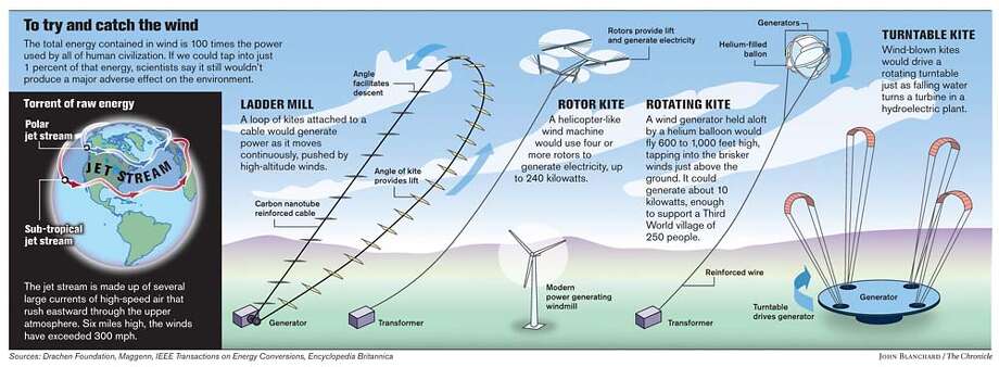
(IV.)Jet stream powered wind mills.
The winds in the jet stream can be in the range of 100 mph, 160 km/hr, 5 to 10 times the common wind speeds at the ground.
Since the power of the turbine varies as the cube power of the speed, this means a wind turbine in the jet stream could provide a hundred to a thousand times more power than one on the ground. A single wind turbine might supply 1 gigawatt of power, enough for an entire city of a million people.
This led to several proposals for harnessing the power of the jet stream:
Scientists look high in the sky for power / Jet stream could fill global energy needs, researchers say
Keay Davidson, Chronicle Science Writer Published 4:00 am PDT, Monday, May 7, 2007
To get to the winds of the jet stream we could use the standard wind mill form of a tall tower with a turbine attached, except we now have the capability to construct those towers to the altitude of the jet stream, ca. 10 km.
As a point of comparison, the Nordex N100/2500 wind turbine generates ca. 2.5 MW using a 100 m wide rotor. The rotor made of carbon composite weighs less than 10 tons. We'll calculate the mass of the tower to 10 km to support that 10 ton weight, using a safety factor of 2 in each case.
For the 350 grade maraging steel, the exponential term in the mass formula is 0.96, so the tower mass to support the 10 ton rotor would be 9.6 tons. For the standard carbon fiber factor, the exponential term would 0.73, for a tower mass of 7.3 tons. And for the boron fiber UD, the exponential term is 0.15, for a tower mass of 1.5 tons.
That 1.5 ton weight using the boron fiber UD is quite remarkable for a tower to reach 10 km high, the altitude jet airliners cruise at. This illuminates how important it is to determine if unidirectional composites can be used for construction of tapered towers.
However, the water turrets on fireboats would not have the "head", i.e., altitude capability, to send the water streams kilometers in the air on their own. In fact, I didn't think such pumps existed. So instead I suggested adding an additional pump that would trade flow rate for altitude. A pump that could do it would be the famous ram or hydraulic ram pump.
I was surprised though after doing a web search that there do exist pumps that do have both high volume and high head. These are so-called "mud pumps" that are used for dredging the sea floor and for pumping out mud and debris deep within mines. In addition to the high volume for dredging and mining purposes, they need the high head since they will also be pumping up mud and rocks, which are denser, so heavier, than just water.
One is the 14-P-220 mud pump. It is capable of 7,500 psi at 375 gpm.
Another thing I didn't realize is such pumps themselves have the capability to vary their psi vs. flow rate values, i.e., they are already able to trade flow rate for head. See for example the table here:
But there is a limit to which a pump's pressure values can be varied. Going beyond that limits the pumps lifetime or can damage it. A psi value of 7,500 psi is 500 bar. This corresponds to a vertical head of 5,000 m. Using the analogy of the ball thrown at a 45 degree angle, the horizontal distance possible would be twice that or 10,000 m, 10 km. It's likely the pump's head can be increased beyond the rated value somewhat at the cost of reduced lifetime, but in any case we can still use the ram pump or other methods to further trade flow rate for distance.
Note, actually for a ball or a water stream, because of air drag or frictional drag in a pipe, the angle for maximum horizontal distance will actually be less than 45 degrees and the distance will be less than twice the vertical height.
In a correspondence, Giottis Motsanos suggested I look into laminar flow to maximize distance. This is when the water flow is in a uniform, parallel stream. I had been assuming the flow had to be within a pipe to maximize distance. But some remarkable instances of laminar flow raise the possibility we can achieve these long distances without using a pipe:
Attached below were some discussions I had on news forums about producing a self-standing tower that can reach to space. It is known current materials do not have sufficient strength-to-weight to accomplish this. So the idea would be to do it dynamically by pressurized fluids pumped upwards. In the ensuing discussion it occurred to me we could also use it to fight forest fires, a currently serious problem here in the U.S.
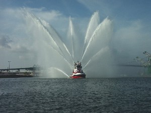
(I.) Calculations suggest we currently have pumps at sufficient power to carry water long distances through piping supported by pressurized water or air. The formula for the power required of a pump to carry a liquid vertically is proportional to its density, flow rate, and altitude, or head, as indicated here: https://www.engineeringtoolbox.com/pumps-power-d_505.html For water, 10 meters, 33 feet, of altitude corresponds to one additional bar of pressure, or 14.7 psi. So the formula for the power of a pump can also be written in terms of pressure. From proportionality, for a pump of a certain rated power, we can trade flow rate for altitude, and vice versa. That is, in order to increase the altitude the water is pumped to by a factor of 10 with the same pumping power, we can decrease the flow rate by a factor of 10. Now consider the pumping power of the fireboat the Warner Lawrence:
It can throw as much as 38,000 gallons per minute 400 feet upwards in the air, using its twin 1,575 horsepower motors and 10 water turrets. Then it could send 3,800 gallons per minute 4,000 feet in the air. Then the idea would be to transport these type of pumping motors, if the ship itself is too difficult to transport, to a lake nearby to a wildfire or even the ocean, which can be several miles away from the fire. These motors would suffice to transport 3,800 GPM to 4,000 foot altitude. The idea would be to then turn the pipes horizontally and angled downward to allow the water to flow horizontally and down to reach the wildfire. The question would then be how is the pipe supported vertically and horizontally? The plan behind this is illustrated by the diagram in post #2 below. Exhaust ports at periodic intervals would direct a (small) proportion of the high pressure water downwards to create an upwards force. How much force? For the vertical portion, the water supports itself by the water pressure. But how about the water pipe? From the 400 foot head of the pumps, this corresponds to about 12 bar pressure above ambient. Now the thrust produced would be analogous to that of a water rocket:
That is, twice the product of the water pressure above ambient times the cross-sectional area. From the appearance of the size of the water turrets, I'll take their diameter as 8", among the largest sizes for hoses used by firefighters.. Each of the 10 turrets at 8" diameter and 12 bar pressure will be converted to an 8" hose at 120 bar pressure. This is 120*100,000 Pascals = 12,000,000 Pa. The diameter of 8", is 0.20 m. Then the total thrust possible would be 2*(12,000,000 Pa)*(π*0.10^2) = 750,000 N, or 76,000 kilogram-force.
It turns out this is the maximum that could be lifted by using the periodically placed exhaust ports along the length of the pipe. The problem is that the horizontal section would be too heavy to be supported by this thrust because for this part you would have to support both the pipe and the water, at least for this pipe size. You could further trade water flow rate for pressure thereby giving greater pressure and increasing thrust and at the same time reducing the water mass that needed to be supported but rather than doing that I'll work with the possibility suggested in post #5 below of sending the water in a parabolic arc. Note this is the path the water would take anyway when sent at the appropriate angle so in this case we should not need to support the water mass. For the pipe mass, let's estimate it first for aluminum. The ratio of the wall thickness of a cylindrical pressure vessel to its radius is in the same proportion as the contained pressure to the vessel material's tensile strength: ______________________________________________________________
Stress in thin-walled pressure vessels
Stress in a shallow-walled pressure vessel in the shape of a sphere is
,
where is hoop stress, or stress in the circumferential direction, is stress in the longitudinal direction, p is internal gauge pressure, r is the inner radius of the sphere, and t is thickness of the sphere wall. A vessel can be considered "shallow-walled" if the diameter is at least 10 times (sometimes cited as 20 times) greater than the wall depth.[14]
Stress in the cylinder body of a pressure vessel.
Stress in a shallow-walled pressure vessel in the shape of a cylinder is
,
,
where:
is hoop stress, or stress in the circumferential direction
is stress in the longitudinal direction
p is internal gauge pressure
r is the inner radius of the cylinder
t is thickness of the cylinder wall.
____________________________________________________________ The tensile strength of standard aluminum is 45,000 psi. The pressure of water at 120 bar would be 1,800 psi, which corresponds to a ratio of 25 to 1. Then the ratio of the wall thickness to the pipe radius would also be 25 to 1, giving a thickness of 0.1 m/25 = 0.004 m. Say the length of the pipe were 10 km, 10,000 m. Then the volume of the pipe wall would be π*0.20*0.004*10,000 = 25 m^3. At an aluminum density of 2,700 kg/m^3 this would weigh, 68,000 kg. This is uncomfortably close to the 76,000 kilo-force that could be supplied by the water flow. Then all but about a tenth of the water would be shooting out of the exhaust ports to support the pipe mass rather than being applied to fight the fire. The situation is made worse when you take into account the frictional losses, especially over long distances. So instead of standard aluminum we'll use other materials that have higher strength-to-weight ratio than standard aluminum. For instance, carbon fiber composites can cut the weight in half for pressure vessels. This would give the pipe a weight in the range of 34,000 kg, and about half the water would be available to fight the fire. This would mean in the range of 1,900 GPM could be applied to the fire. Note that a common 5" diameter fire hose might only supply 500 GPM so this would be like four 5" size fire hoses being applied simultaneously and continuously to the fire. The weight for the pipe might be actually smaller by an additional factor of 2. The reason is as the water gets higher the pressure reduces so the required thickness of the pipe can also be reduced. If the pipe were straight it would be exactly half, but in curved parabolic shape the degree of reduction would need to be calculated. Also, as noted in post #5 below it may be the weight of the pipe will be supported by the flow of the water anyway and we might only need the exhaust ports for stability. This happens for example with those "air dancers":
We still need to calculate the frictional losses however. For each of the ten 8" pipes the initial inflow would 1/10th of the total 3,800 GPM, or 380 GPM. This page gives a frictional loss calculator: Hazen-Williams Equation - calculating Head Loss in Water Pipes. https://www.engineeringtoolbox.com/hazen-williams-water-d_797.html For an 8" pipe, of 10,000 m, 32,500 ft, length, and 380 GPM flow rate, the loss by this calculator is only 38 psi out of the 1,800 psi. The pumps for the Warner Lawrence were only used as an example of what could be done. It could also be done by other large size pumps, such as this:
https://www.rainforrent.com/HighFlowPumps-DV600c.aspx This can pump 28,000 GPM with a head of 96 feet. It is meant to be portable despite its 27,000 pound weight. I have said that water flow rate can be traded for altitude for a given pump power. But I didn't actually say how to do that. Certainly you can make the pump to begin with that can reach such high altitudes and also have high flow rates as needed in this application of fighting wildfires. But pumps don't commonly come with this kind of combination of ratings. For water pumps with pressure ratings in the thousands of psi these are usually just used for pressure washers or for waterjet cutting systems. In such cases the water flow rate is small. But to use this for fighting the current wildfires, rather than waiting for pumps of this special type to be designed, developed, tested and manufactured, which might take years, we need another method that can be implemented quickly. There is a rather well known method for converting water flow rate for altitude: the ram pump, or hydraulic ram. This is a rather simple type of pump that does not even need a motor. It works by using water flowing downhill to provide the energy to drive a smaller amount of water uphill to an even greater height than the initial water source, i.e., it trades water flow rate for altitude: Hydraulic Ram. "A hydraulic ram, or hydram, is a cyclic water pump powered by hydropower. It takes in water at one "hydraulic head" (pressure) and flow rate, and outputs water at a higher hydraulic head and lower flow rate. The device uses the water hammer effect to develop pressure that allows a portion of the input water that powers the pump to be lifted to a point higher than where the water originally started. The hydraulic ram is sometimes used in remote areas, where there is both a source of low-head hydropower and a need for pumping water to a destination higher in elevation than the source. In this situation, the ram is often useful, since it requires no outside source of power other than the kinetic energy of flowing water." https://en.wikipedia.org/wiki/Hydraulic_ram Ram pumps are of such simple construction that they are often made by amateurs either for their water pump needs or simply for experiment. See for example here:
How to build a RAM PUMP.
They can also be rather easily made of large size:
Largest Ram Pump in the World.
There is at least one other company investigating pumping water up to high altitudes to fight fires, though in this case it's only going up vertically and only to 900 feet. The water hose in this case is only being supported by a drone:
As mentioned there these methods would allow fighting fires in high rises at heights above which normal fire trucks can reach with their hoses. They would allow the hoses to even be sent inside the buildings at high floors to direct the water to the specific locations inside the buildings of the fire. They also could be use for rescue for heights beyond which firetruck ladders can reach. They could have prevented tragedies such as the Grenell Tower fire in London.
Another application would be drought relief when a fresh water source is miles away, and also for natural disasters such as hurricanes and earthquakes when normal water service is interrupted.
And it's not just areas of unexpected drought or natural disasters. Many areas in the developing nations suffer from fresh water scarcity. In these areas a significant part of the day is devoted simply to walking miles to reach a source of fresh water and carrying it back, just as a way of life. The people of these communities could accomplish much more without having to spend hours just transporting water.
Note for this application, unlike the fire fighting application, most of the energy for transporting it could be recovered. For you could attach turbines at the bottom of the pipe to gain energy from the falling water. Some of the energy would be lost, due to frictional losses. But considering that much of the energy could be recovered, it's likely the water transport could be powered by solar power alone.
(II.) The original impetus of this work was to produce a self-standing tower to reach the altitude of space, 100 km or above. The payload that could be launched would be increased significantly in that case. However, the pressures required for a single pump to accomplish this would for a large amount of water flow would be impractical.
The suggestion instead was to do the pumping in stages, as illustrated in post #2. You would need lightweight pumps that would be supported by the pressurized flow exiting the exhaust ports.
I'll discuss a small pump to serve as a proof-of-principle to reach, say, 10 km. A low cost example of the individual pumps that might work is the battery operated Worx 325 psi Hydroshot, at 0.5 GPM, 0.5 in hose diameter, running at 20 volts, 2 amps.
At the 325 psi = 2,210,000 Pa pressure and a 0.5 in diameter hose, this could generate a thrust of 2*(2,210,000 Pa)*π*(0.25/39.37 m)^2 = 560 N, 57 kilogram-force. The pump only weighs 3.7 pounds, 1.7 kg.
As before, we'll suppose the water itself is self-supported by the pressurized, directed upwards, water stream so we need to determine the weight of the pipe. Again using aluminum as a baseline, its 45,000 psi tensile strength is about 140 times the 325 psi internal pressure of the pipe. So the thickness of the pipe wall would be the size of the pipe radius 0.25 divided by 140: 0.25/140 = 0.001785 in. And the wall volume of a 10 km = 10,000 m pipe, with the diameter and thickness converted to meters, would be
π*(0.5/39.37)*(0.001785/39.37)*10,000 m = 0.018 m^3. At a 2,700 kg/m^3 density of aluminum this would weigh 49 kg. Likely, we'll want to reduce the weight by half by using carbon fiber composite instead, so 25 kg.
How many of the pumps would we need? The 22 bar pressure of the pump could send a water stream 21 bar*10 = 210 meters in the air. Say we put a pump every 200 meters, then to go the full 10,000 m length we would need 50 pumps.
Given the 25 kg weight for the full 10,000 m length of the carbon fiber pipe, each of the fifty 200 m long segments would only weigh 0.5 kilo.
The water thrust sent out the exhaust ports would need to support the 1.7 kg weight of the Worx, the 0.5 kg weight of the 200 m long pipe segment, and the battery. Say, we use a 0.3 kg battery, for a total weight of 2.5 kg. Then this is only a fraction of 2.5/57 of the full weight that can be supported. But since this is being exhausted out the ports, this same fraction 2.5/57 of the 0.5 gallon per minute of the flow would be lost.
Note also though this same fraction would be lost for each of the 50 stages. So the amount remaining at the end would be (1 - (2.5/57) )^50 = 0.1 of the original 0.5 GPM, or 0.05 GPM.
As for the run time for the battery, commonly non-rechargeable lithium batteries can get 500 watt-hours per kilogram, and rechargeable lithiums about 250 wh per kilo. So a 0.3 non-rechargeable battery would have 150 wh. The 400 watt Worx can then run for 0.375 hours, 22 minutes. For the rechargeable battery it would be half that.
This would be for a proof-of-principle demonstration to show you can reach thousands of kilometers at a relatively low cost. There are pressure washers though that put out thousands of psi, not just 325 psi, and put out 2 or more gallons per minute, not just 0.5 GPM. These could be used to reach the 100 km altitude for space.
They can also be combined at hundreds of pumps at each stage to produce a water stream of sufficient flow to fight forest fires.
Another possibility is offered by a new development called the Pyrolance. It uses ultra high pressure water to cut through brick and concrete for the purposes of firefighting. It operates at up to 20 GPM and 1,450 PSI. Ten of these combined just on the ground, i.e., without staging, could be used to generate a kilometers long stream to fight forest fires.
There is also another pressure washer that operates at even high pressures, at 40,000 psi. This puts out 11 GPM, the VORTEX™ 36-9950-15A:
Still, for higher altitudes and for longer distances it would better to use staging. The problem is significant amounts of water can be lost using the exhaust ports method to keep the pipe aloft.
I mentioned before the other company that proposes using a drone to keep the water hose aloft. You would need extra engines though for this. But if you're giving the water all this energy to reach high altitude why not use it as well to keep the pipe aloft? One way that would not lose water through the exhaust ports would have a turbine inside the pipe that would turn with the water flow. This turbine could then be connected through gears to propellers on the outside to support the pipe in the air.
Another way would be to use a turbine or paddle wheel on the inside to connect to a piston on the outside. The piston would compress air, then release the air when a sufficient level of compression was reached to act like a compressed air rocket.
I suggested in the posts on that thread of using pressurized fluid, liquid or gas, supplied from the ground to provide propulsion to a rocket and/or to support a tower to high altitude. The *principle* behind this of using pressurized fluid supplied from the ground to provide the thrust has now been demonstrated, if not to high altitude:
Fluid Motion: JetLev-Flyer H2O-Propelled Jet Pack By Chuck Squatriglia February 02, 2009 | 5:02:03 PM