Showing posts with label Aluminum-Lithium. Show all posts

Tuesday, July 10, 2018

DARPA's Spaceplane: an X-33 version, Page 3.

Copyright 2018 Robert Clark

 In the previous post "DARPA's Spaceplane: an X-33 version, Page 2", I discussed some recent high strength metal alloys that might give the X-33 and VentureStar even lighter weight propellant tanks than originally envisioned. Still, because of the conformal, noncylindrical shape of the tanks, they would still not have the weight efficiency of a cylindrically shaped rocket. Then I'll discuss some methods that will come close to having the weight efficiency of cylindrical tanks.

Multi-tubed Propellant Tanks.
 One possibility would be to achieve the same lightweight tanks as cylindrical ones by using multiple, small diameter, cylindrical tubes. 

 A similar idea is described here:

OCTOBER 1, 2009 | MECHANICAL & FLUID SYSTEMS
Assemblies of Conformal Tanks
Space is utilized efficiently and sloshing is reduced.
This Prototype Assembly of Conformal Tanks was built to demonstrate the feasibility of building such an assembly to fit an approximately toroidal available volume.
https://www.techbriefs.com/component/content/article/tb/techbriefs/mechanics-and-machinery/5780

 You could get the same volume by using varying lengths and diameters of the multiple cylinders to fill up the volume taken up by the tanks. The cylinders would not have to be especially small. In fact they could be at centimeter to millimeter diameters, so would be of commonly used sizes for tubes and pipes.

 The weight of the tanks could be brought down to the usual 35 to 1 ratio for aluminum-lithium hydrogen/oxygen propellant to tank mass. Then the mass of the tanks on the X-33 would be 210,000 lbs/35 = 6,000 lbs, saving 9,200 lbs off the vehicle dry weight. This would allow the hydrogen-fueled X-33 to achieve its originally desired Mach 15 maximum velocity.

 But note that since now the tanks are composed of cylindrically-shaped tubes, we no longer have the problem of the conformally-shaped carbon composite tanks failing. Then we could get in the range of 50 to 1 propellant to tank mass ratio by using carbon composites for the cylindrically-shaped tubes, and we could reduce the dry mass due to the tanks by an additional 2,000 lbs.

 The same multi-tube approach applied to the full-scale VentureStar would allow it to significantly increase its payload carrying capacity. At a 35 to 1 aluminum-lithium ratio of propellant mass to tank mass for cylindrical tanks, the 1,929,000 lbs propellant mass would now require a mass of only 1,929,000/35 = 55,000 lbs for the tanks, a saving of 83,000 lbs off the original tank mass. This could go to extra payload, so from 45,000 lbs max payload to 128,000 lbs max payload.

 But again we could now use carbon-composites for the cylindrical tubes. This would shave an additional 16,000 lbs off the weight of the tanks, and increase the payload now to 144,000 lbs.

 An analogous possibility might be to use a honeycombed structure for the entire internal makeup of the tank. The X-33's carbon composite tank was to have a honeycombed structure for the skin alone. Using a honeycomb structure throughout the interior might result in a lighter tank in the same way as does multiple cylinders throughout the interior.

 For the multi-tube approach and the honeycombed variant there would be a significant problem for maintenance however. As this is intended to be reusable, we would have difficulty examining all the interior parts of the tanks for cracks or punctures. 

 If you removed the many layers of the multi-tube method layer by layer for examination that would involve significant time and expense. Even more importantly by so many times having to physically move one of the layers of tubes you run an increased risk of damaging one of the tubes. 

 One possibility is that since there would be a gap space between one tube and a tube positioned diagonally to it, we could use this space to insert high resolution imaging equipment. It might also work to insert x-ray imaging devices.

Partitioned Propellant Tanks to Save Weight.
  A different approach to getting near cylindrical-tube weight efficiency, might be to model the tanks, viewing them vertically, as conical but with a flat front and back, and rounded sides. Then the problem with the front and back naturally trying to balloon out to a circular cross section might be solved by having supporting flat panels at regular intervals within the interior. 

 The X-33 composite tanks did have support arches to help prevent the tanks from ballooning but these only went partially the way through into the interior. You might get stronger a result by having these panels go all the way through to the other side.
These would partition the tanks into portions. This could still work if you had separate fuel lines, pressurizing gas lines, etc. for each of these partitions and each got used in turn sequentially. A preliminary calculation based on the deflection of flat plates under pressure shows with the tank made of standard aluminum alloy and allowing deflection of the flat front and back to be only of millimeters that the support panels might add only 10% to 20% to the weight of the tanks, while getting similar propellant mass to tank mass ratio as cylindrical tank. 

 Note you might not need to have a partitioned tank, with separate fuel lines, etc., if the panels had openings to allow the fuel to pass through. These would look analogous to the wing ribs in aircraft wings that allow fuel to pass through. You might have the panels be in a honeycomb form for high strength at lightweight that still allowed the fuel to flow through the tank. Or you might have separate beams with a spaces between them instead of solid panels that allowed the fuel to pass through between the beams

 We'll view the X-33 hydrogen tanks standing vertically as conical with flattened front and back and rounded sides. This report on page 19 by the PDF file page numbering gives the dimensions of the X-33 hydrogen tanks as 28.5 feet long, 20 feet wide and 14 feet high:

Final Report of the X-33 Liquid Hydrogen Tank Test Investigation Team.
https://web.archive.org/web/20120127103443/http://alpha.tamu.edu/public/jae/misc/tankreport.pdf

 Call it 9 meters long, 6 meters wide, and 4.3 meters deep for this calculation. I'll simplify the calculation by approximating the shape as rectangular, i.e., uniformly 6 meters wide. Note that the rounded portions of the sides, top, and bottom will be considered separately. I'll call the vertical length of each section x, and the bulkhead thickness h. Since the length of the tank is 9m, the number of sections is 9/x.


 Typically propellant tanks are pressurized in the 20-40 psi range. I'll take it as 30 psi; call it 2 bar, 2x10^5 Pa. Referring to the drawing of the tank, each bulkhead takes part in supporting the internal pressure of the two sections on either side of it. This means for each section the internal pressure is supported by one-half of each bulkhead on either side of it, which is equivalent to saying each bulkhead supports the internal pressure of one section.

 The force on each section is the cross-sectional area times the internal pressure, so 6m*x*(2*10^5 Pa), with x as in the diagram the vertical length of each section. The bulkhead cross-sectional area is 6m*h, with h the thickness of the bulkheads. Then the pressure the bulkheads have to withstand is 6m*x*(2*10^5 Pa)/6m*h = (2*10^5 Pa)*x/h.

 The volume of each bulkhead is 6m*h*4.3m. The density of aluminum-lithium alloy is somewhat less than aluminum, call it 2,600 kg/m^3. So the mass of each bulkhead is (2,600 kg/m^3)*6m*h*4.3m = 67,080*h. Then the total mass of all the 9/x bulkheads is (9/x)*67080*h = 603,720*(h/x).

 Note that additionally to the horizontal bulkheads shown there will be vertical bulkheads on the sides. These will have less than 1/10 the mass of the horizontal bulkheads because the length of each section x will be small compared to the width of 6m, and will have likewise small contribution to the support of the internal pressure.

 The tensile strength of some high strength aluminum-lithium alloys can reach 700 MPa, 7*10^8 Pa. Then the pressure the bulkheads are subjected to has to be less than or equal to this: (2*10^5 Pa)*x/h <= 7*10^8 Pa, so x/h <= 3,500, and h/x => 1/3,500. Therefore the total mass of the bulkheads = 603,720*(h/x) => 172.5 kg. Note we have not said yet how thick the bulkheads have to be only that their total mass is at or above 172.5 kg, for one of the twin rear tanks. It's twin would also require 172.5 kg in bulkhead mass. The third, forward, tank had about 2/3rds the volume of these twin rear tanks so I'll estimate the bulkhead mass it will require as 2/3rds of 172.5 kg, 115 kg. Then the total bulkhead mass would be 460 kg, about 15% of the 3,070 kg tank mass I calculated for the reconfigured X-33.

 This is for the bulkheads resisting the outwards pressure of the sections. Notice I did not calculate the pressure inside the tank on the bulkheads from the propellant on either side. This is because the pressure will be equalized on either side of the bulkheads. However, we will have to be concerned about the pressure on the rounded right and left sides of the tank, and the rounded top and bottom of the tank, where the pressure is not equalized on the outside of the tank.

 Before we get to that, remember the purpose of partitioning the tank was to minimize the bowing out of the front and back sides from the internal pressure. Consider this page then that calculates the deflection of a flat plat under a uniform load:

eFunda: Plate Calculator -- Clamped rectangular plate with uniformly distributed loading.
This calculator computes the maximum displacement and stress of a clamped (fixed) rectangular plate under a uniformly distributed load.
http://www.efunda.com/formulae/solid_mechanics/plates/calculators/CCCC_PUniform.cfm

 In the data input boxes, we'll put 200 kPa for the uniform load, 6 meters for the horizontal distance, .3 m, say, for the vertical distance, and 6 mm for the thickness of the plate. For the vertical distance x I'm taking a value proportionally small compared to the tank width, but which won't result in an inordinate number of partitioned sections of the tank. For the thickness I'm taking a value at 1/1000th the width of the tank, which is common for cylindrical tanks. For the material specifications for aluminum-lithium we can take the Young's modulus as 90 GPa. Then the calculator gives the deflection as only 2.35mm, probably adequate.

 However, we still have to consider what happens to the rounded sides and the bottom and top. Look at the last figure on this page:


Thin-Walled Pressure Vessels.

http://www.efunda.com/formulae/solid_mechanics/mat_mechanics/pressure_vessel.cfm

 It shows the calculation for the hoop stress of a cylindrical pressure vessel. The calculation given is 2*s*t*dx = p*2*r*dx, using s for the hoop stress. This implies, s = p*r/t, or equivalently t = p*r/s. So for a given material strength s, the thickness will depend only on the radius and internal pressure.

 However, what's key here is the same argument will apply in the figure if one of the sides shown is flat, instead of curved. Therefore in our scenario, the rounded sides, top and bottom, which we regard as half-cylinders, will only need the thickness corresponding to a cylinder of their same diameter, i.e., one of a diameter of 4.3m. 

 So the rounded portions actually require a smaller thickness than what would be needed for a cylinder of diameter of the full 6m width of the tank.

 This means the partitioned tank requires material of somewhat less mass than a cylindrical tank of dimension the full width of the tank plus about 15% of that mass as bulkheads.

 The new high strength metal alloys might also save further on this weight. However, we now have to consider the Young's modulus of the alloys, because of the deflection of the plates calculation, and not just the tensile strength.

A Key Advantage of Partitioned Tanks.
 There is an another advantage of using partitioned tanks in addition to the weight savings. A problem with weight growth of the X-33/VentureStar arose in regards to the size of the wings. For stability reasons, you would want the center of gravity (CG) to remain ahead of the center of pressure (CP) during the entire flight. But as the propellant is burned off, the propellant mass near the front will be decreased and this will increase the effect of the heavy engines at the rear on the moving the CG rearward. To deal with this problem during the X-33 development, the wings kept getting larger and larger. But this cancels out the advantage the X-33 had in its dry mass in its original design in not needing heavy wings.

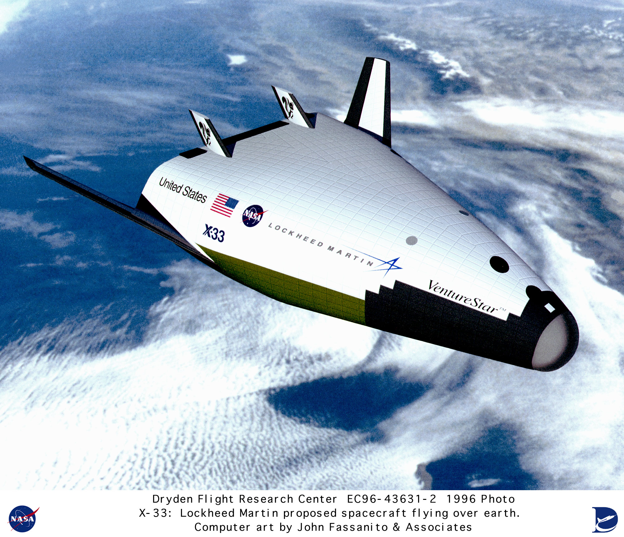
 The original X-33/VentureStar was supposed to look like this:


 But in the later incarnations, it looked like this:
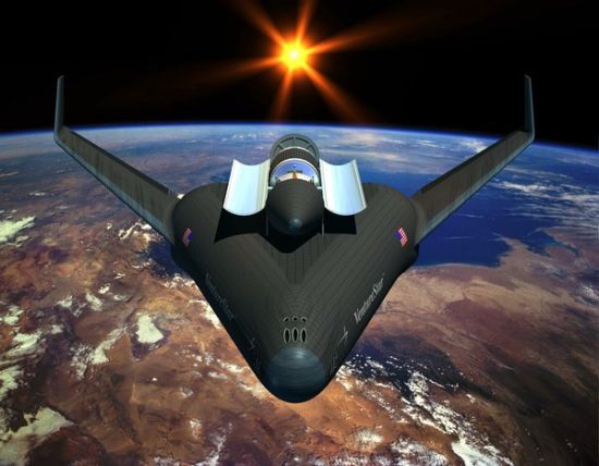

 The added wing size was to move the CP rearward to keep the CG ahead of it. 

 Partitioned propellant tanks are nothing new actually in aerospace. They are quite commonly used on jet airliners to deal with the problem of CG shift as fuel is burned off:

Concorde.
Balancing by Fuel-Pumping.
The Concorde Tank-Schematic:
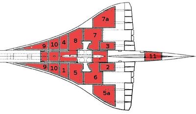
"1 + 2 + 3 + 4 are the Collector-Tanks, feeding the engines directly. Usually they feed there counterpart engines – but they can be cross-switched to feed more and/or other engines at the same time.
5 + 7 and 8 + 6 are the Main-Transfer Tanks, feeding the 4 Collector-Tanks. Initially 5 + 7 are active. If those are empty 6 + 8 take over (or must be activated from the Engineering Panel!).
5a + 7a are Auxiliary-Tanks (to 5 and 7).
9 + 10 are the Trim-Tanks for balancing forward
11 is the Trim-Tank for balancing afterward"

 Then the partitioned tanks could solve two problems of the dry mass of the X-33/VentureStar: weight growth in the tanks and in the wings.


 Bob Clark

Friday, May 29, 2015

A Vertical Landing SSTO - a "Space Shuttle" NASA Missed.

Copyright 2015 Robert Clark


Saturn V's S-II second stage as an SSTO.
The S-II stage during stacking operations of Apollo 6 in the VAB
  
The Saturn V launcher of the Apollo program was remarkable in the lightweight features of its upper stages, the S-II and the S-IVB. This page gives a list of the fueled weights and empty weights of the Saturn V stages:

Ground Ignition Weights

  The mass efficiency of the upper stages led to some proposals to use them together as an independent launcher, the Saturn II:


 However, when this Saturn II was proposed there were not high performance hydrolox engines that could operate at sea level. Therefore it was designed to use the upper stage engine already used on the Saturn V upper stages, the J-2. Since this was not designed to operate at sea level though, this limited the performance of the rocket.

 But in the late 70's when the space shuttle was being designed and built the high performance Space Shuttle Main Engine , the RS-25, was developed. Interestingly, if SSME's were used on the S-II stage you would get a fully reusable rocket as an SSTO that would have comparable payload to orbit as the space shuttle, i.e., no solid rocket boosters required.

 The later versions of Apollo had improved weight optimization. We'll use the specifications for Apollo 14. The "Ground Ignition Weights" page gives the Apollo 14 S-II dry weight as 78,120 lbs., 35,510 kg, and gross weight as 1,075,887 lbs., 489,040 kg, for a propellant mass of 997,767 lbs., 453,530 kg. 

 The SSME has a mass of 3,500 kg while the J-2 had a mass of 1,788 kg. We'll replace the 5 J-2's used on the S-II with 3 SSME's. This increases the stage dry mass by 1,560 kg. We'll use Dr. John Schillings Launch Performance Calculator to estimate the payload to LEO. 

 Enter in 37,070 kg for the stage dry mass, with the new SSME's replacing the J-2's. Enter in 453,530 kg for the propellant mass. Enter in the vacuum thrust with the max thrust at the 109% level in kilonewtons as 3*2,280 kN = 6,840 kN. Enter in the vacuum Isp of 452.3 s. Select "No" for the "Restartable Upper Stage" option, otherwise the payload will be reduced. And enter in an inclination of 28.5 degrees to match the latitude of the Cape Canaveral launch site of 28.5 degrees.

 Then the calculator gives the mass to LEO as 27,077 kg:

Mission Performance:
Launch Vehicle:  User-Defined Launch Vehicle
Launch Site:  Cape Canaveral / KSC
Destination Orbit:  185 x 185 km, 28 deg
Estimated Payload:  27077 kg
95% Confidence Interval:  18536 - 37061 kg

"Payload" refers to complete payload system weight, including any necessary payload attachment fittings or multiple payload adapters

Heat Shield and Landing Legs.
  We'll envision this as a VTVL (vertical take-off vertical landing) SSTO. Then we need to add heat shield, and landing legs. For weight of the heat shield, from the Apollo era it was about 15% of the weight of the reentry vehicle. However, SpaceX's Pica-X is about half the weight so about 8%. One scenario would be for the heat shield to be at the top with the stage entering top first and rotating to put the bottom down after reentry as with this proposal by SpaceX for the Falcon 9 upper stage:


 For the landing legs, that is commonly estimated as 3% of the landed weight:


 However, with modern composite materials we can probably get it to be half that. So call it 1.5%. 

Hovering capability for a VTVL vehicle.
 It was always taken as a given that a reusable VTVL rocket should have hovering capability. See for instance this discussion between noted space historian Henry Spencer and Mitchell Burnside Clapp who worked on both the DC-X and X-33 programs:


 Hovering ability and the low thrust capability this requires allows fine control of both the attitude and velocity in 3-dimensions for unexpected winds on landing. If you don't have that then that limits your ability to make small, fast corrections to attitude and velocity. The result will be repeated over-corrections and over-corrections to those over-corrections until time and space run out:

Hovering capability for the reusable Falcon 9.

 As with the Falcon 9 case, even one SSME would have too much thrust to allow this vehicle to hover. As discussed in the "Hovering capability for the reusable Falcon 9" post, you could apply various attachments to one of the engines to reduce the thrust on landing. You would though have to arrange the engines to be a in a straight-line to have a center engine rather than the clustered arrangement used on the Space Shuttle.

RL-10's as Landing Engines.
 Another possibiliuty to allow hovering would be to use multiple small engines for the landing. The RL-10A5 engine used on the DC-X would work. This is a version of the RL-10 with a shortened nozzle to operate at sea level:

RL-10A-5.

 We'll use eight of them at the bottom of the stage arranged around the outer rim. Since the S-II stage had a 10 meter diameter these would still fit underneath the stage whether the three SSME's were arranged in the clustered format as with the Space Shuttle or in a straight-line.

 These will add 8*143 kg = 1,144 kg to the dry mass, but using them also at launch will add 8*64.70 kN = 517.6 kN to the vacuum thrust.

 Calculated Stage Weight for the Reusable Rocket.
  Adding on the 1,144 kg to the dry mass gives 38,214 kg. At 1.5% of the landed weight for the landing legs this would be 0,015*38,214 kg = 573 kg additional weight to the stage. The estimated propellant that needs to be kept on reserve for landing as discussed in the "horizontal vs. vertical landing" link, is about 10% of the landed weight. This would be about 3,879 kg reserve propellant. This plus the landing legs brings the reentry mass to 42,665 kg. The heat shield weighs 8% of this to bring it to 46,079 kg. 

Calculated Payload for the Reusable Rocket.
 We'll enter in now into the Schilling calculator 46,079 kg for the dry mass, subtract off the 3,879 kg kept on reserve from the propellant mass, and add on 517.6 kN onto the vacuum thrust. The result is:

Mission Performance:
Launch Vehicle:  User-Defined Launch Vehicle
Launch Site:  Cape Canaveral / KSC
Destination Orbit:  185 x 185 km, 28 deg
Estimated Payload:  18706 kg
95% Confidence Interval:  10073 - 28808 kg

"Payload" refers to complete payload system weight, including any necessary payload attachment fittings or multiple payload adapters

This is an estimate based on the best publicly-available engineering and performance data, and should not be used for detailed mission planning. Operational constraints may reduce performance or preclude this mission.


 This is less than the shuttle, but we can increase the payload as was done with the shuttle by using aluminum-lithium alloy for the propellant tank. This can shave off 25% from the propellant tank weight.

Payload Increase on Switching to Aluminum-Lithium Tanks.
 The propellant tanks on the S-II weighed 3% of the total stage weight:
SP-4206 Stages to Saturn
7. The Lower Stages: S-IC and S-II
S-II CONFIGURATION
The S-II turned out to be a comparatively advanced stage in terms of the existing state of the art. Although the S-II carried about 426 400 kilograms of liquid oxygen and liquid hydrogen, the tank structure, though supporting the structural mass, accounted for just a shade over three percent of the stage's total fueled weight. A common bulkhead much larger than that in any previous rocket averted the need for an [212] interstage between the oxidizer and fuel tanks; this reduced the total length of the stage by over 3 meters and saved about 4 metric tons of extra weight. In technical terms, the fabrication of the bulkheads called for unusually demanding accuracy in meridian welds that joined the bulkhead gores together. The welding operation joining the curved, 6-meter-long seams together had to be made to specifications allowing less than 0.33 millimeter of a mismatch. Then there was the problem of insulating the big liquid hydrogen tank, filled with thousands of liters of the super-cold propellant. Otherwise, the basic design elements of the S-II seemed conventional enough in that it consisted of eight major structural components and six major systems, all of which reflected the usual kind of basic elements associated with both the S-IC and the S-IVB.28
http://www.apolloproject.com/sp-4206/xch7.htm

  Then the 3% of the S-II gross mass of 489,040 kg would be 14,671 kg for the propellant tank mass. A 25% savings by switching to Al-Li would be 3,667 kg. This would bring the payload to 22,373 kg, about the same as the Space Shuttle.


  Bob Clark


Saturday, September 28, 2013

Budget Moon Flights: Ariane 5 as SLS upper stage, page 2.

Copyright 2013 Robert Clark


 In the blog post Budget Moon Flights: Ariane 5 as SLS upper stage, I noted that using an Ariane 5 core stage would be a quick and low cost means of getting a higher payload capacity than the 70 mT NASA was giving for the 2017 SLS first launch. This would make it much easier to conduct a manned lunar lander mission using the SLS. However, finally, NASA has acknowledged that the Block 1, first version of the SLS to launch in 2017 will have a 90+ mT payload capacity not the 70 mT always stated by NASA:

SLS Dual Use Upper Stage (DUUS).
http://ntrs.nasa.gov/archive/nasa/casi.ntrs.nasa.gov/20130013953_2013013757.pdf

 This is important since it means we will have the capability to do manned lunar landing missions by the 2017 first launch of the SLS:

SLS for Return to the Moon by the 50th Anniversary of Apollo 11, page 5: A 90+ metric ton first launch of the SLS.
http://exoscientist.blogspot.com/2013/09/sls-for-return-to-moon-by-50th.html

  Still, because of the even higher payload possible using an upper stage, NASA might still want to consider getting a quick and low cost upper stage by using the Ariane 5 core. In that "SLS Dual Use Upper Stage (DUUS)" report are given some specifications for the DUUS. They state they want a highly weight optimized stage, which the Ariane 5 core would certainly fulfill. The Vulcain engine though has thrust size about twice that of the specified 100 - 120K lb range, and the 170 mT of propellant is also larger than the specified 130 mT propellant load. However, these are so much superior to the specified requirements it should result in significantly greater payload delivery than the stated 130 mT to LEO, perhaps to the 150 mT range.
 However, a problem is the 18.3 m specified max height. The Ariane 5 core is at 30.5 m height. Likely the height limitation is coming from limitations on the size and height of the facilities during stage integration. I'll find out if that is a firm limit.
 We could cut down the size of the Ariane 5 core to make it 130 mT in propellant load. Proportionally this would bring the height down to about 20 m, closer to the max. height. It turns out that shortening a stage is rather easy technically so this should still be doable by the 2017 first launch of the SLS.
 Another possibility would be to use the same propellant tank tooling for this DUUS stage as that used by NASA to make the 8 meter wide SLS tank, while using the other components such as the engine of the Ariane 5. However, the idea is to get a low cost upper stage in a short time frame. This might be a costly modification that might also be difficult to manage by the 2017 SLS first launch.
 This possibly though could open up an additional means of lightweighting the stage. We could use aluminum-lithium alloy instead of the standard aluminum used for the Ariane 5. NASA is also planning to use standard aluminum for the SLS core. But as I discuss in SLS for Return to the Moon by the 50th Anniversary of Apollo 11, page 4: further on lightweighting the SLS core, new versions of Al-Li have been developed that could be used for this purpose.
 However, due to the natural inertia of large agencies it might be difficult to change the decision and go with Al-Li for the SLS core. But this decision might be easier to make in regards to the smaller upper stage which wouldn't need as much of the more expensive Al-Li and for which getting a lightweight stage is a much greater priority.

  Bob Clark


Wednesday, July 17, 2013

Budget Moon Flights: Ariane 5 as SLS upper stage.

Copyright 2013 Robert Clark

Delta IV Heavy Orion Circumlunar Test Flight.
I’m fairly sure looking at the capabilities of the Delta IV Heavy with the upgraded RS-68a engine, about 28 metric tons to LEO, that it could launch the Orion on that 2014 test launch on an actual circumlunar flight, not just to 3,600 miles out as currently planned. A circumlunar flight would result in a much more capable test of the Orion.

The Orion test is planned to only carry a dummy service module, so that will be much lighter. The flight is planned though to carry the launch abort system (LAS) so that detracts from the weight that can be launched.

Without the LAS the DIVH could definitely send the Orion on a circumlunar flight. With the LAS, it makes it a little more difficult to estimate since it is jettisoned before reaching orbit.

This makes the use of the SLS for that unmanned circumlunar test flight in 2017 even more dubious, since the DIVH could do that, even if removing the LAS is required. That is another reason why I argue NASA should be aiming for an actual unmanned lunar landing test with that 2017 SLS flight.

Low Cost Lunar Lander and Crew Module.
ULA has done studies on adapting the Centaur upper stage as a lunar lander stage so you would not need a huge, and hugely expensive, Altair lander. We already even have a crew module that could be used for such a lander in NASA’s SEV, which can be ready by 2017 for test flights:


Inside NASA’s New Spaceship for Asteroid Missions | Space.com.
by Clara Moskowitz, SPACE.com Assistant Managing Editor
Date: 12 November 2012 Time: 02:30 PM ET

If the current schedule holds, NASA could test-drive a version of the SEV at the International Space Station in 2017. http://www.space.com/18443-nasa-asteroid-spacecraft-sev.html

Ariane 5 Core as SLS Upper Stage.
NASA is considering a version of the upper stage to be used with the Block II version of the SLS that uses RL-10 engines instead of the J-2X:

SLS prepares for PDR – Evolution eyes Dual-Use Upper Stage.
June 1, 2013 by Chris Bergin
http://www.nasaspaceflight.com/2013/06/sls-pdr-evolved-rocket-dual-upper-stage/

This is expected to save on costs.

NASA also wants to encourage European participation in the proposed asteroid retrieval mission:

NASA Pitches Asteroid Capture To International Partners.
By Frank Morring, Jr.
Source: Aerospace Daily & Defense Report
June 28, 2013
http://www.aviationweek.com/Article.aspx?id=/article-xml/asd_06_28_2013_p01-01-592208.xml

Then a way to save further on development costs and to get European involvement would be to use the Ariane 5 core as the upper stage. It’s of common-bulkhead design to save mass. I recently learned it also uses the pressure-stabilized, “balloon tank”, method a la the Centaur to further save on tank mass.

The ESA also believes its Vulcain II engine can be made air-startable since this was planned for the Liberty rocket. The Vulcain uses a rather short nozzle since it is meant for ground launch, giving it a 432 s Isp. But simply giving it a nozzle extension would give it the ca. 462 s ISP of the RL-10.

Another key advantage is that because little additional development would be needed it might even be ready by the 2017 first launch of the SLS. Then this first 2017 launch of what was only to be a 70 mT interim version could have the 100+ mT capability of the later versions of the SLS. Such a version would clearly have the capability to do manned lunar lander missions.

You could also give this stage the RL-10 engines, instead of the Vulcain. The Vulcain weighs about 1,800 kg. Four RL-10′s would weigh 1,200 kg. So this would save 600 kg off the stage dry mass.

The NasaSpaceFlight.com article mentions the advantage of having different diameters for the hydrogen and oxygen tanks to maintain commonality with tooling of existing stages, and that is the reason for not having both tanks the same diameter. That would not be a problem of course with using the Ariane 5 core at a common 5.4 meter diamter. And someone noted on the Nasaspaceflight forum thread on this topic that for a uniform 8.4 m diameter, NASA could just use the same tooling for both that is used for the 8.4 meter SLS core stage tank.

For any of these possibilities it would be very good if NASA could use the composite tanks Boeing is investigating. Aerospace engineer Jon Goff on his blog noted ULA estimated their ACES proposed upgrade of the Centaur could get a 20 to 1 mass ratio by switching to aluminum-lithium for the tanks. And according to Boeing, an additional 40% can be saved off the Al-Li tank mass by using composites, resulting in an even larger mass ratio than 20 to 1:


NASA Sees Potential In Composite Cryotank.
By Frank Morring, Jr. morring@aviationweek.com
Source: AWIN First
July 01, 2013
http://www.aviationweek.com/Article.aspx?id=/article-xml/awx_07_01_2013_p0-592975.xml


Scaling up your stage mass, such as to the DUUS size, is also known to be able to improve your mass ratio. Imagine then all these mass ratio improving factors being applied. How high could the mass ratio get, perhaps to the 25 to 1, or even 30 to 1 range???

Imagine what you could do with a hydrolox stage with an ISP as high as ca. 462 s with a mass ratio as high as 30 to 1. (*)

Bob Clark


(*) By rocket equation, the delta-v is:  462*9.81ln(30) = 15,400 m/s.


Update, Sept. 28, 2013:

 Finally, NASA has acknowledged that the Block 1, first version of the SLS to launch in 2017 will have a 90+ mT payload capacity not the 70 mT always stated by NASA:

SLS Dual Use Upper Stage (DUUS).
http://ntrs.nasa.gov/archive/nasa/casi.ntrs.nasa.gov/20130013953_2013013757.pdf

 This is important since it means we will have the capability to do manned lunar landing missions by the 2017 first launch of the SLS:

SLS for Return to the Moon by the 50th Anniversary of Apollo 11, page 5: A 90+ metric ton first launch of the SLS.
http://exoscientist.blogspot.com/2013/09/sls-for-return-to-moon-by-50th.html

Saturday, April 6, 2013

SLS for Return to the Moon by the 50th Anniversary of Apollo 11, page 4: further on lightweighting the SLS core.

                                             Copyright 2013 Robert Clark

 NASA has decided to revert to the original Al 2219 aluminum alloy that was first used on the shuttle external tank for the SLS core:


SLS takes on new buckling standards, drops Super Light alloy.
February 18, 2013 by Martin Payne 
http://www.nasaspaceflight.com/2013/02/sls-new-buckling-standards-drops-super-light-alloy/

 This is due to the greater brittleness of the lighter aluminum-lithium alloys used on the later super lightweight ET tank (SLWT). And because the later alloys were not available in the greater thickness needed for optimal lightweight performance. 
 However, NASA itself estimated the Al-li alloys could save 25% off the weight of a propellant tank over the Al 2219 alloy:

RELEASE : 09-096
NASA Uses Twin Processes to Develop New Tank Dome Technology
http://www.nasa.gov/centers/langley/news/releases/2009/09-096.htm

 Still NASA estimated in regards to the SLS tank, reverting back to the Al 2219 alloy would only cost 3,000 kg in lost payload, much smaller than 25%. Apparently, the reduced thickness of the plates available for the aluminum-lithium alloys used on the SLWT results in reduced weight efficiency. 
 However, a new aluminum-lithium alloy Al-Li 2050 has similar strength at lightweight to the SLWT alloys and is available in thicker plate sizes:

Shell Buckling Knockdown Factor (SBKF) Project Update.
http://www.nasa.gov/offices/nesc/home/Feature_ShellBuckling_Test.html

 Then we could recover the ca. 25% saving over using the Al 2219 alloy. This now is a significant increase in payload, beyond just 3,000 kg. The original ET tank using Al 2219 alloy weighed 35,000 kg. The new SLS tank is scaled up 33%, so under the same Al 2219 alloy would weigh in the range of 46,000 kg. Then the new Al-Li alloy saving 25% off this would be a saving of 11,500 kg. 
 NASA made an assessment of cost benefit analysis and decided on the older Al 2219 alloy. But this is Apollo era, 1960's, technology. This is going backwards not forwards in our technological development. 
 Further weight saving can be achieved by using composites for the intertank. NASA with Boeing is investigating large cryogenic composite tanks. This is still a research project. However the intertank is an unpressurized structure. Structures like this have been made of composites for decades. 
 To estimate the weight that can be saved, note the intertank in the al-li SLWT weighed 5,500 kg:

Single Stage To Orbit Mass Budgets Derived From Propellant Density and Specific Impulse.
John C. Whitehead
32nd AIAA/ASME/SAE/ASEE Joint Propulsion ConferenceLake Buena Vista, FL July 1-3, 1996
http://www.osti.gov/bridge/servlets/purl/379977-2LwFyZ/webviewable/379977.pdf

 Then the intertank of the SLS of 33% larger size may be estimated to weigh 7,300 kg. A new composite material known as an isotruss saves significantly on weight:


 It weighs less than 1/7th that of aluminum at the same strength. This would reduce the intertank mass to less than 1,000 kg. This would subtract off an additional 6,000 kg from the tank mass to bring it down to 28,500 kg. This is nearly 18,000 kg in total off from the original SLS tank weight, which could go to extra payload.
 As I mentioned in the blog post SLS for Return to the Moon by the 50th Anniversary of Apollo 11, page 3: lightweighting the SLS core, internal NASA estimates put the actual payload of the SLS as significantly above the 70 mT mark often cited by NASA. Then an additional 18,000 kg added to this payload capability would put the SLS payload to LEO at ca. 100 mT. This is important because it would mean the SLS would have the capability to do manned lunar lander missions, not just lunar flybys.
 NASA administrator Charles Bolden has said NASA, meaning the administrators, has no plans on a Moon mission, being more focused on a mission to an asteroid. However, the public in general, space advocates, industry, and even NASA's own ranks have shown no interest in the asteroid mission:


Back to the Moon? Not any time soon, says Bolden.
By Jeff Foust on 2013 April 5 at 1:05 pm ET
A week from Monday marks the third anniversary of President Obama’s speech at the Kennedy Space Center where he formally announced the goal of a human mission to an asteroid by 2025. While that is an official goal of NASA’s human space exploration program, there remains some opposition or, at the very least, lack of acceptance of the goal by many people, including some with NASA, as a report on NASA’s strategic direction concluded last December.
At a joint meeting of the Space Studies Board and the Aeronautics and Space Engineering Board in Washington on Thursday, the head of that study, Al Carnesale of UCLA, reiterated those concerns. “Since it was announced, there was less enthusiasm for it among the community broadly,” he said of the asteroid mission goal. “The more we learn about it, the more we hear about it, people seem less enthusiastic about it.”
Carnesale suggested that, in his opinion, it might be better to shelve the asteroid mission goal in favor of a human return to the Moon. “There’s a great deal of enthusiasm, almost everywhere, for the Moon,” he said. “I think there might be, if no one has to swallow their pride and swallow their words, and you can change the asteroid mission a little bit… it might be possible to move towards something that might be more of a consensus.”
http://www.spacepolitics.com/2013/04/05/back-to-the-moon-not-any-time-soon-says-bolden/

 The SLS even by its first mission in 2017 can do manned lunar landing missions by incorporating well known and relatively low cost weight saving methods to its core and upper stages.
 This would go a long way towards garnering support both among the public and those in  industry to know that a return to the Moon is in the offing and in the very near term.


  Bob Clark


Update, Sept. 28, 2013:

 Finally, NASA has acknowledged that the Block 1, first version of the SLS to launch in 2017 will have a 90+ mT payload capacity not the 70 mT always stated by NASA:

SLS Dual Use Upper Stage (DUUS).
http://ntrs.nasa.gov/archive/nasa/casi.ntrs.nasa.gov/20130013953_2013013757.pdf

 This is important since it means we will have the capability to do manned lunar landing missions by the 2017 first launch of the SLS:

SLS for Return to the Moon by the 50th Anniversary of Apollo 11, page 5: A 90+ metric ton first launch of the SLS.
http://exoscientist.blogspot.com/2013/09/sls-for-return-to-moon-by-50th.html

Friday, March 29, 2013

The Coming SSTO's: multi-Vulcain Ariane.

Copyright 2013 Robert Clark


 The option the ESA decided on for the planned Ariane 6 was the version using a solid propellant first stage:

CNES, ASI Favor Solid-Rocket Design For Ariane 6.

By Amy Svitak
Source: Aviation Week & Space Technology
October 15, 2010

 However,  one of the other options discussed for the Ariane 6 would also allow manned European flight capability. This would be the two Vulcain core version.


CNES is evaluating these three launch vehicle concepts for a next-generation Ariane 6: two based on solid-rocket-motor technology plus an all-liquid-fueled launcher with optional solid-motor boosters. (Credit: CNES)

 To estimate the payload capability for the twin Vulcain core I'll use John Schillings launch performance calculator:

Launch Vehicle Performance Calculator.

http://www.silverbirdastronautics.com/LVperform.html

 In the calculations for this multi-Vulcain Ariane core stage, I used this page for the specifications on the Ariane:


Space Launch Report:  Ariane 5 Data Sheet.
http://www.spacelaunchreport.com/ariane5.html#config


 For the Vulcain 2 specifications, I've seen different numbers in different sources, though close to each other. I'll use this source:

 I'll also use the earlier Ariane 5 "G" version that is lighter than the current "E" version to be lofted by two Vulcains without side boosters. According to the SpaceLaunchReport page it had a 170 mT gross mass for the core at a 158 mT propellant load, giving a 12 mT dry mass.
 According to the Astronautix page, Vulcain 2 has a 434 s vacuum Isp and 1350 kN vacuum thrust. So two will have a 2700 kN vacuum thrust. The Vulcain's mass is listed as 1,800 kg. So adding another will bring the stage dry mass to 13,800 kg.
Now input this data into Schilling's calculator. Select again default residuals and select "No" for the "Restartable Upper Stage?" option. Select the Kourou launch site for this Ariane 5 core rocket. For the orbital inclination, I input 5.2 degrees. I gather Schilling uses this for Kourou's latitude since deviating from this decreases the payload. I chose also direct ascent for the trajectory.
Then the result I got was 7,456 kg(!) to orbit:

================================
Mission Performance:
Launch Vehicle:     User-Defined Launch Vehicle
Launch Site:     Guiana Space Center (Kourou)
Destination Orbit:      185 x 185 km, 5 deg
Estimated Payload:      7456 kg
95% Confidence Interval:      4528 - 10898 kg
================================

 We should be able to remove a component on the Ariane 5 core to lighten the weight for this application. Ed Kyle on his Spacelaunchreport.com page discusses the Liberty rocket that had been planned to use a SRB first stage and an Ariane 5 core second stage. For the Liberty application, a forward skirt on the core called the JAVE ("Jupe AVant Equipée") that transmits the forces of the two solid boosters to the core would be removed. This will also be removed for our application without solid boosters.
 The JAVE massed 1,700 kg. So our payload could be increased to 9,156 kg. However, Kyle also discusses on his page on the Liberty rocket that the increased thrust from the SRB first stage would require thicker walls on the Ariane core now used as an upper stage.
 The thicker walls on the Ariane 5 core for the Liberty rocket are indicated in this video:


 The 5-segment SRB to be used on the Liberty rocket has 12 times the thrust of the Vulcain engine. Yet as seen in the video the increased thickness to handle the increased axial load is only 50%. Then only doubling the thrust by adding a second Vulcain quite likely will require a much smaller increase in thickness. I'm informed that the 158 mT propellant mass tank has a dry weight in the range of 4,400 kg. So even increasing the thickness 50% increases the weight by ca. 2,200 kg, and the payload would still be approx. 7,000 kg.  A problem with this estimate though, aside from the unknown accuracy of the video, is that it is based on the larger Evolution "E" version of the Ariane 5 core, which might not require as much strengthening to handle the higher thrust loads as the smaller "G" version.  So we'll use a formula for calculating the thickness of a propellant tank based on the axial load as given on this lecture page: Launch Vehicle Design: Configurations and Structures. Space System Design, MAE 342, Princeton University Robert Stengel http://www.princeton.edu/~stengel/MAE342Lecture4.pdf  on page 9:
  From the first formula the critical buckling load without the pressurization effect is:   σc,w/o pressure = [9(t/R)1.6 + 0.16(t/L)1.3]*E.   Multiplying out the second formula for critical buckling with the pressurization effect you see it's:   σc,w/ pressure = σc,w/o pressure + 0.191p(R/t).   Now use the formula on p. 8 that relates the tensile strength of the material to the thickness required of a pressurized tank:
   You see that  σhoop = p(R/t)  so that the formula above becomes:     σc,w/ pressure = σc,w/o pressure + 0.191σhoop .   Now use values for the tensile strength of aluminum alloy. The aluminum alloy used on the Ariane 5 core tanks, Al 2219, happens to get stronger at cryogenic temperatures:
 Table taken from Properties of Aluminum Alloys: Tensile, Creep, and Fatigue Data at High and Low Temperatures, page 86. The table gives the aluminum alloy strength at liquid hydrogen temperatures as 685 MPa and elasticity modulus, E, as 85 GPa.  For the Ariane 5 core "G" version, the hydrogen tank walls are only 1.3 mm thick, while the oxygen's, 4.7 mm. The diameter of the tanks is 5.4 m. Because of its extreme wall thinness it's the hydrogen tank whose stress has to be limited. It's length is about 18 m. Then the formula for the critical buckling load without pressurization gives: σc,w/o pressure = [9(t/R)1.6 + 0.16(t/L)1.3]*E = [9(0.0013/2.7)1.6 + 0.16(0.0013/18)1.3]*85*109 = 3,800,000 Pa.  And the additional buckling strength due to pressurization is 0.191σhoop = 0.191*685,000,000 = 130,800,000 Pa, for a total critical buckling load of 134,600,000 Pa.  The maximum thrust of two Vulcain 2's will be 2,700,000 N. The cross-sectional area of the hydrogen tank walls is 2*π*R*t = 2(3.14)(2.7)(0.0013) = 0.022 m2 . Then the maximum axial pressure is 2,700,000/0.022 = 123,000,000 Pa.  This is indeed less than the critical buckling load of 134.6 MPa. However, for a manned launcher a safety factor of 1.4 is usually included. This will require the maximum axial pressure to be less than 96 MPa. This requires a wall thickness of 1.6 mm, about a 25% increase. This still only increases the tank weight by 1,000 kg, so the payload becomes now ca. 8,000 kg, still quite high for a SSTO. Remember also switching to aluminum-lithium alloy can save as much as 25% off the dry weight which would bring us again to the 9,000 kg payload range.


   Bob Clark

Could Blue Origin develop a lander for Artemis III?

Copyright 2025 Robert Clark SpaceX is coming under increasing criticism for its delay in developing the Starship lunar lander: U.S. Is Losin...