Sunday, December 28, 2014

A liquid-fueled Indian manned launcher. UPDATED.

Copyright 2014 Robert Clark


 India is progressing towards manned spaceflight:

India debuts GSLV Mk.III with prototype crew capsule.
December 17, 2014 by William Graham


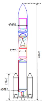
 The current plan is for a 2021 launch for the manned system. However, the most recently developed rocket the GSLV Mk. III uses two large solid side boosters. Space engineers in general do not like solid rockets for manned launchers since they can not be shut down. However, there is an all liquid alternative for India for a manned launcher that actually would be cheaper than the GSLV Mk. III.

 It would use 4 of the liquid-fueled strap on boosters used on the earlier design the GSLV Mk. II attached to the GSLV Mk. III core stage. We'll use the specifications on the GSLV Mk. II and GSLV Mk. III on Ed Kyle's SpaceLaunchReport.com page. The strap-ons for the GSLV Mk. II have a gross mass of 48.2 metric tons (mT) and propellant mass of 42.6 mT so a dry mass of 5.6 mT. The vacuum thrust of the single Vikas 2 engine is 70,360 kgf, 690 kN, with a vacuum Isp of  281 s. 

 The gross mass of the GSLV Mk. III is 125 mT with a propellant load of 110 mT, so a dry mass of 15 mT. The vacuum thrust of the two Vikas 2 used is 140,720 kgf, 1380 kN. The cryogenic upper stage has a gross mass of 30 mT, with a propellant load of 25 mT, so a dry mass of 5 mT. It's engine CE-20 engine has a thrust of 20,000 kgf, 196 kN, with an Isp of 450 s.
  
 Input this data into Dr. John Schilling's Launch Performance Calculator. Select the Satish Dhawan launch site and a launch inclination of 13.9 degrees to match the latitude of the launch site. Then the calculator gives a payload to LEO of:

Mission Performance:
Launch Vehicle:  User-Defined Launch Vehicle
Launch Site:  Satish Dhawan Space Center
Destination Orbit:  185 x 185 km, 14 deg
Estimated Payload:  6493 kg
95% Confidence Interval:  4829 - 8498 kg

"Payload" refers to complete payload system weight, including any necessary payload attachment fittings or multiple payload adapters
This is an estimate based on the best publicly-available engineering and performance data, and should not be used for detailed mission planning. Operational constraints may reduce performance or preclude this mission.


 About 6,500 kg. It is notable though reading the description of the failed launches of the GSLV on the SpaceLaunchReport.com page that some involved engine failures. There would need to be multiple successful unmanned launches of this configuration before it is certified for manned launches.


  Bob Clark

UPDATE, January 15, 2015:

 I found that the www.spaceflight101.com site provides more accurate info on the GSLV Mk. II and GSLV Mk. III launchers than the Spacelaunchreport.com page. Using these values gives an even better performance for this proposed all-liquid launcher.

 The GSLV Mk. II side boosters have specifications listed as:

                                 Boosters

# Boosters4
TypeLH40
Length19.7m
Diameter2.1m
Inert Mass~5,600kg
Launch Mass47,600kg
Tank MaterialAluminium Alloy
FuelUH25 - 75% UMDH, 25% Diazane
OxidizerNitrogen Tetroxide
Propulsion1 Vikas 2
Thrust763kN
Impulse293 sec
Engine Dry Weight900kg
Engine Length2.87m
Engine Diameter0.99m
Burn Time148sec
Chamber Pressure58.5bar
Mixture Ratio1.7 (Ox/Fuel)
Attitude ControlSingle-Plane Engine Gimbaling
Stage SeparationWith Core Stage

 The GSLV Mk. III core stage has specifications listed as:

Core Stage

TypeL-110
Length21.26m
Diameter4.0m
FuelUnsymmetrical Dimethylhydrazine
OxidizerNitrogen Tetroxide
Inert Mass10,600kg
Propellant Mass115,000kg
Launch Mass125,600kg
Propellant TanksAluminum Alloy
FuelUH25 - 75% UDMH, 25% Diazane
OxidizerNitrogen Tetroxide
Propulsion2 Vikas 2
Thrust (SL)677kN
Thrust (Vac)766kN
Specific Impulse293 sec
Engine Dry Weight900kg
Engine Length2.87m
Engine Diameter0.99m
Chamber Pressure58.5bar
Mixture Ratio1.7 (Ox/Fuel)
Turbopump Speed10,000rpm
Flow Rate275kg/s
Area Ratio13.88
Attitude ControlEngine Gimbaling
IgnitionT+110s
Burn Time200s
Stage SeparationActive/Passive Collets

 The cryogenic upper stage has specifications listed as:


Cryogenic Upper Stage

TypeC-25 Cryogenic Upper Stage
Length13.32m
Diameter4.0m
FuelLiquid Hydrogen
OxidizerLiquid Oxygen
Inert Mass~4,000kg
Propellant Mass25,000kg
Launch Mass~29,000kg
Propellant TanksAluminum Alloy
PropulsionCE-20
Engine TypeGas Generator
Thrust - Vacuum200kN
Operational Range180-220kN
Specific Impulse Vac443s
Engine Mass588kg
Chamber Pressure60bar
Mixture Ratio5.05
Area Ratio100
Thrust to Weight34.7
Burn Time580s
GuidanceInertial Platform, Closed Loop
Attitude Control2 Vernier Engines
Restart CapabilityRCS for Coast Phase

  Plugging these dry mass, propellant mass, and Isp values into the Schilling calculator gives these results:

Mission Performance:
Launch Vehicle:  User-Defined Launch Vehicle
Launch Site:  Satish Dhawan Space Center
Destination Orbit:  185 x 185 km, 14 deg
Estimated Payload:  9005 kg
95% Confidence Interval:  7106 - 11299 kg

"Payload" refers to complete payload system weight, including any necessary payload attachment fittings or multiple payload adapters

This is an estimate based on the best publicly-available engineering and performance data, and should not be used for detailed mission planning. Operational constraints may reduce performance or preclude this mission.


 A payload of 9,000 kg is quite high. It's close to the 10,000 kg payload of the GSLV Mk. III without needing the two huge, expensive solid side boosters the Mk. III uses. Note also this all-liquid configuration with 4 liquid side boosters is similar to that of the venerable Soyuz launcher used for decades for manned launches.

 To get a faster operational manned rocket we might use the smaller cryogenic upper stage already used on the GSLV Mk. II. On the December 2014 test flight of the GSLV Mk. III, its cryogenic stage was still in development and was not part of the test. So to use all operational stages instead we could use the Mk. II's cryogenic stage. It's specifications are listed as:

                                  Third Stage

TypeGS3 - C15
Inert Mass~2,500kg
Launch Mass~15,300kg
Length8.7m
Diameter2.8m
Tank MaterialAluminium Alloy
FuelLiquid Hydrogen
OxidizerLiquid Oxygen
Propellant Mass12,800kg
GuidanceInertial Platform, Closed-Loop
Propulsion1 ICE (CE-7.5)
CycleStaged Combustion
Thrust (Vacuum)73.5 to 93.1kN
Impulse454sec
Engine Dry Weight435kg
Engine Length2.14m
Engine Diameter1.56m
Burn TimeUp to 1,000sec
Chamber Pressure58bar
Attitude Control2 vernier Jets, each 2kN
RCS for Coast Phases
Stage SeparationMerman Band, Hot Staging

   Inputting these specifications instead into the Schilling calculator gives:

Mission Performance:
Launch Vehicle:  User-Defined Launch Vehicle
Launch Site:  Satish Dhawan Space Center
Destination Orbit:  185 x 185 km, 14 deg
Estimated Payload:  6810 kg
95% Confidence Interval:  5373 - 8577 kg

"Payload" refers to complete payload system weight, including any necessary payload attachment fittings or multiple payload adapters

This is an estimate based on the best publicly-available engineering and performance data, and should not be used for detailed mission planning. Operational constraints may reduce performance or preclude this mission.


  The 6,800 kg payload is still high, sufficient for a manned launcher.

   Bob Clark
 

Saturday, November 29, 2014

A half-size Ariane for manned spaceflight.

Copyright 2014 Robert Clark

 The current agreed  upon design for the Ariane 6 is to use a slightly reduced in size Ariane 5 core with strap-on solid boosters about half-size to the solids used on the Ariane 5:

Ariane 6.

   I believe this is a preferred solution for the Ariane 6 than the version using all solid lower stages. For one thing, if SpaceX succeeds in producing a reusable first stage, then ESA can keep pace by making the core stage of the Ariane 6 reusable.

 My ideal solution however would have used two to three Vulcain engines on the core stage. This would have an additional advantage of being able to be used as a manned launcher with no solids attached:

Friday, March 29, 2013
The Coming SSTO's: multi-Vulcain Ariane.
Copyright 2013 Robert Clark
http://exoscientist.blogspot.com/2013/03/the-coming-sstos-multi-vulcain-ariane.html


Single-Stage To Orbit Case. Still we can get a manned launcher retaining a single Vulcain II on the core and shrinking the size of the stage, to half-size. As discussed in the "The Coming SSTO's: multi-Vulcain Ariane" post, the propellant mass of the Ariane 5G core is 158,000 kg, with a 12,000 kg dry mass. We may remove a forward skirt called the "JAVE" used to attach the solids to the Ariane 5. This massed 1,700 kg bringing the dry mass down to 10,300 kg. The propellant tank on the Ariane 5G weighed 4,400 kg. So half-size this will weigh 2,200 kg, bringing the dry mass down to 8,100  kg. 
 In Dr. John Schilling's Launch Performance Calculator, enter in now also 79,000 kg for the propellant mass, 1,350 kN for the vacuum thrust and 434 s for the vacuum Isp. Select Kourou as the launch site with a launch inclination of 5.2 degrees, to match the launch site latitude. The "Restartable Upper Stage" option should be checked "No" even for a single stage, otherwise the payload will be reduced. Then the calculator gives:


Mission Performance:
Launch Vehicle:  User-Defined Launch Vehicle
Launch Site:  Guiana Space Center (Kourou)
Destination Orbit:  185 x 185 km, 5 deg
Estimated Payload:  2528 kg
95% Confidence Interval:  1064 - 4248 kg
"Payload" refers to complete payload system weight, including any necessary payload attachment fittings or multiple payload adapters
This is an estimate based on the best publicly-available engineering and performance data, and should not be used for detailed mission planning. Operational constraints may reduce performance or preclude this mission.

  This payload of 2,500 kg is for a single stage to orbit vehicle. As discussed in the blog post "Budget Moon flights: lightweight crew capsule", this may be sufficient for a 3-person capsule to LEO. For instance the Cygnus capsule given life support may fit within this size range. I have discussed though an SSTO reaches its best performance when using altitude compensation: "Altitude compensation attachments for standard rocket engines, and applications".

 By using altitude compensation the vacuum Isp can be raised to 466 s and the vacuum thrust to 1,350 kN*(466/434) = 1,450 kN. Schilling's calculator now gives a result of: 

Mission Performance:                  
Launch Vehicle:  User-Defined Launch Vehicle
Launch Site:  Guiana Space Center (Kourou)
Destination Orbit:  185 x 185 km, 5 deg
Estimated Payload:  4544 kg
95% Confidence Interval:  2894 - 6480 kg
"Payload" refers to complete payload system weight, including any necessary payload attachment fittings or multiple payload adapters
This is an estimate based on the best publicly-available engineering and performance data, and should not be used for detailed mission planning. Operational constraints may reduce performance or preclude this mission.


 As discussed in the "altitude compensation" blog post though characteristics of how the Schilling calculator makes its estimates may make it less accurate in a scenario using altitude compensation. A more accurate analysis that varies the Isp from ground to orbit may be needed in this case.

Two-Stage To Orbit Case.

 We can get a higher payload manned launcher by making it TSTO. We'll use the cryogenic upper stage the Ariane H10-3. The Astronautix page gives it a gross mass of 12,310 kg and dry mass of 1,570 kg, for a propellant mass of 10,740 kg. The Isp is listed as 446 s with a vacuum thrust of 62.70 kN. However, this extra mass for the upper stage would mean the single Vulcain II on the core could not loft it.


 Then we'll reduce the propellant load in the core stage. It might also work to run the Vulcain at some percentage above the rated thrust, or use a varied mixture ratio at launch compared to high altitude. But using a reduction of the propellant load method, we'll lessen the propellant in the first stage by the mass of the upper stage, so by 12,310 kg. This brings the propellant load of the first stage to 66,690 kg. There is about a 35 to 1 ratio of propellant to tank mass so this will reduce the tank mass of the first stage by 12,310 kg/35 =350 kg. Then the dry mass of the core becomes 7,750 kg.  Then the calculator gives:


Mission Performance:
Launch Vehicle:  User-Defined Launch Vehicle
Launch Site:  Guiana Space Center (Kourou)
Destination Orbit:  185 x 185 km, 5 deg
Estimated Payload:  4891 kg
95% Confidence Interval:  3970 - 5982 kg
"Payload" refers to complete payload system weight, including any necessary payload attachment fittings or multiple payload adapters
This is an estimate based on the best publicly-available engineering and performance data, and should not be used for detailed mission planning. Operational constraints may reduce performance or preclude this mission.


 We'll also estimate the payload for the altitude compensation case. Again take the first case vacuum thrust as 1,450 kN and the vacuum Isp as 466 s. But also improve the thrust and Isp for the upper stage, The thrust becomes 62.70 *(466/446) =  65.5 kN, with vacuum Isp also 466 s. Then the Schilling calculator gives:


Mission Performance:
Launch Vehicle:  User-Defined Launch Vehicle
Launch Site:  Guiana Space Center (Kourou)
Destination Orbit:  185 x 185 km, 5 deg
Estimated Payload:  6075 kg
95% Confidence Interval:  5016 - 7334 kg

"Payload" refers to complete payload system weight, including any necessary payload attachment fittings or multiple payload adaptersThis is an estimate based on the best publicly-available engineering and performance data, and should not be used for detailed mission planning. Operational constraints may reduce performance or preclude this mission.

 Again however this estimate for the altitude compensation case would have to be confirmed with more accurate estimation methods.


  Bob Clark

Saturday, November 15, 2014

Altitude compensation to allow the use of American engines on the Antares rocket.

Copyright 2014 Robert Clark

 In the blog post "Altitude compensation attachments for standard rocket engines, and applications", I noted that the idea that altitude compensation was only useful for SSTO's prevented their implementation and therefore their usefulness for multi-stage rockets was not realized. 

 An example of this is Orbital Sciences Antares rocket. The failed flight of the Antares in October, 2014 put renewed emphasis on the choice of 1960's era Russian engines AJ-26/NK-33. It is understandable why they were used since on the key performance metric of Isp, at 330+ s they were significantly better than American engines, at ca. 300 s. 

 However, by using altitude compensation the Isp of the low performance American rocket engines can even exceed that of the Russian engines. Orbital Sciences has decided not to use anymore of the Russian-derived engines on the Antares, and therefore need a replacement engine. I suggest investigating altitude compensation attachments that can made to already existing American engines so would be relatively low cost to implement.

 One possible engine that could be used would be the Rocketdyne RS-27A. It is used on the venerable Delta II rocket. Rocketdyne claims a 100% reliability record for the engine. You would need three of them though at ca. 200,000 lbs. thrust to make up for the two AJ-26/NK-33 engines at ca. 300,000 lb. thrust.

 How high could we get with the Isp on the RS-27A using altitude compensation? At an area ratio of only 12 to 1, the RS-27A only gets a vacuum Isp of 302 s. To see how much better we can do with a larger nozzle, we might make a comparison to the Russian RD-58, which gets a vacuum Isp of 349 s by using a high area ratio of 189 to 1 with not a particularly high chamber pressure of 78 bar. A better comparison might be to the Russian RD-0124 with a vacuum Isp of 359 s, but at a high chamber pressure of 162 bar. Unfortunately the area ratio of this engine is not specified, but it is certain to be high since it is an upper stage engine.

 Actually for vacuum Isp, just having a high nozzle area ratio is more important than the chamber pressure, a high chamber pressure being needed to insure a high sea level Isp. As a point of comparison, the hydrogen fueled RL-10B2 has only a chamber pressure of 39 bar but by using a nozzle extension to bring the area ratio to 280 to 1, it gets the highest Isp of any chemical engine at 465.5 s.

 Support for the idea a high area ratio on a kerosene engine can get a vacuum Isp of ca. 360 s even with a low chamber pressure is provided by the Rocket Propulsion Analysis program. Using the free Lite version you can estimate some fairly accurate vacuum Isp's for rocket engines, the sea level estimates though for the free version being not so accurate. Here are results using the specifications given on the Astronautix page on the RS-27A:


  The "Optimum Expansion" Isp number I've found to be a relatively accurate estimate for the actual vacuum Isp of existing engines. By the way, the negative values for the "Sea level" Isp are coming from the fact there would be severe losses for a low chamber pressure engine using such a large expansion ratio nozzle.

 Now compare this to the results if the chamber pressure were say 160 bar:


 You see the large increase in chamber pressure only adds minimally to the vacuum Isp, though it would have a great effect on the sea level Isp.

  So we'll take the vacuum Isp of the RS-27A with an adaptive nozzle attachment as 360 s. Now to calculate how much payload we can get on the Antares with these new engines I'll use the original's dry mass and propellant mass specifications here: Antares Launch Vehicle Information. The dry mass  of the first stage is given as 18,700 kg and the gross mass as 260,700 kg. 

 The two AJ-26 engines weighed 1,200 kg each for a total of 2,400 kg. The RS-27A weighs 1,000 kg, So three will be 3,000 kg. So the dry mass raises to 19,300 kg and the gross mass to 261,300 kg. I am assuming the adaptive nozzles can be made lightweight so as not to significantly increase the engine weight. The three RS-27A's though will have a lower liftoff thrust than the two AJ-26's. To make up for that I'll use a higher efficiency upper stage such as the hydrogen-fueled Ariane 4 H10-3 rather than the solid Castor stage now used.

 Now consider that we are assuming our adaptive nozzle will allow near optimal expansion from sea level to vacuum. Then note the RS-27A is a later edition of the RS-27 where the area ratio was increased from 8 to 1 to 12 to 1 to improve the vacuum Isp. But this reduces the sea level performance. The sea level Isp and thrust were reduced from 264 s and 93,357 kilogram-force (kgf) for the RS-27 to 255 s and 90,770 kgf for the RS-27A. But considering our adaptive nozzle I'll assume we are able to also get the 264 s Isp and 93,357 kgf thrust at sea level or perhaps do even better with a shorter nozzle equivalent at sea level. 

  At a 93,357 kgf liftoff thrust the total thrust at liftoff would be 280,071 kgf. The H10-3 stage has a gross mass of 13,100 kg. Then the total mass without payload will be 261,300 kg + 13,100 kg = 274,400 kg. This would result in a rather low thrust/weight ratio at liftoff which will reduce payload capacity through gravity drag.

 A couple of ways to improve this liftoff T/W ratio. First note on the page on the Antares linked above the specifications include the thrust at 108% of the "rated thrust". This is rather common that an engine can actually operate at a few percentage points above its rated thrust. This is the case for example with the Space Shuttle Main engines. If the RS-27A with adaptive nozzles can operate at 108% of its rated thrust that would bring the sea level thrust to 302,476 kgf.

  Another way to improve the liftoff T/W would be to reduce the propellant load by say 20,000 kg. As we'll see below the payload would still be rather high.

 We'll use Dr. John Schilling's launch performance calculator to estimate the payload possible. Select the Wallops launch site in the calculator and input the "inclination, deg" as 38, to match the Wallops site latitude.

 The calculator uses the vacuum values for the Isp and thrust inputs. This will be raised to 360 s for the Isp with our adaptive nozzles. But note also this increase in vacuum Isp also results in an increase in the vacuum thrust by a factor of the ratio of the Isp's, that is, by a factor of 360/302. Then the three RS-27A with adaptive nozzles will have vacuum thrust (360/302)*3*1054.20 kN = 3,700 kN.

 Input also the specifications for the Ariane 4 H10-3 for the second stage in the calculator. The HM7-B engine used on that stage has a vacuum Isp of 447 s. Then the results are:

Mission Performance:
Launch Vehicle:  User-Defined Launch Vehicle
Launch Site:  Wallops Flight Facility
Destination Orbit:  185 x 185 km, 38 deg
Estimated Payload:  9458 kg
95% Confidence Interval:  7735 - 11589 kg

 The estimate of 9,458 kg is nearly twice the payload of the current Antares. Notably though this is using the high efficiency hydrogen-fueled upper stage.

 To address the low liftoff T/W I mentioned one way was to reduce the propellant load by, say, 20,000 kg. Doing this results in a payload of:

Mission Performance:
Launch Vehicle:  User-Defined Launch Vehicle
Launch Site:  Wallops Flight Facility
Destination Orbit:  185 x 185 km, 38 deg
Estimated Payload:  8764 kg
95% Confidence Interval:  7166 - 10736 kg

 Still a pretty high result.  

 A consideration in regards to the accuracy of this estimate however is the effect of the altitude-compensating high vacuum Isp compared to the assumptions that go into the calculator. The Schilling calculator takes the vacuum Isp and thrust as inputs and automatically takes into account the reductions at sea level. However, since it assumes it is using a fixed nozzle it would assume the sea level Isp and thrust are much closer to the vacuum values than they would be in this scenario. On the other hand the altitude compensating nozzle would not have the losses of a fixed nozzle. Then more accurate payload calculators that take into account the variations of Isp and thrust with altitude would need to be used to get a more accurate estimate of the payload to orbit.


  Bob Clark

Saturday, November 8, 2014

Safety problems in the flight procedures for SpaceShipTwo.

Copyright 2014 Robert Clark

 Recent reports are that the co-pilot on the failed SpaceShipTwo flight unlocked the feathering mechanism early:

Two pilots who were close friends, now tied together by one fatal flight.
By Christian Davenport and Jöel Glenn Brenner November 3  
http://www.washingtonpost.com/news/business/wp/2014/11/03/two-pilots-who-were-close-friends-now-tied-together-by-one-fatal-flight/

 This article says the co-pilot "realized his error" after unlocking the feather and tried to shut down the engine. But it could be he noticed the feather deployed when it shouldn't have even when unlocked, and he then tried to shut down the engine.

 The flight procedures were that the feather should be unlocked at Mach 1.4, not at the Mach 1 it was unlocked on this flight. However, it is not known how much this was explained to be a mission critical element to the pilots. It may have been this was simply treated as something to do to follow the set timeline. Were there training sessions where this was explained that if you do this beforehand it will lead to vehicle disintegration? It is hard to imagine the pilots would make that mistake if it were emphasized the mission critical importance of when the feathering was unlocked.


 This article also quotes a Scaled Composites pilot as stating that normally the co-pilot would announce when Mach 1.4 was reached and the pilot would acknowledge it and command the feather to be unlocked. However, tape of an earlier SpaceShipTwo flight shows this didn't happen on that flight either.


 From the audio you can hear that one pilot state he is unlocking the feather when the motor is still burning. The feather doesn't deploy, correctly, until it is commanded to do so later after the rocket has ceased burning:


SpaceShipTwo's Intense Rocket Ride - Tail View and Cockpit Recording | Video.
Published on Sep 6, 2013

A camera was strapped to the rear of the Virgin Galactic vehicle to capture footage of the rocket engines and feather system at work. The vehicles 2nd powered flight occurred on September 5th, 2013.


 However, it is not announced that Mach 1.4 has been reached when it is unlocked. It is simply stated the feather has been unlocked by one of the pilots and the other acknowledges it.


 A key problem from listening to the video is that the pilots are not calling out the speed and altitude at any time during the burn. The only time they call out the altitude is a few seconds after the engine cutoff when they are close to max altitude. Note that when landing jet airliners when speed and altitude are both critical to a safe landing the pilots are calling these out to ensure they are within the correct range. The pilots should also be calling out both speed and altitude during the engine burn of SS2 to insure this mission critical step of the unlocking is done only at the right time.


 Another problem with the flight procedures also becomes apparent from this video. During that flight in September, 2013, the feathering was unlocked at about 16 seconds into the engine burn, and the feathering deployed correctly only later after engine cutoff. 


 But in the failed flight the catastrophic unlocking occurred only 9 seconds into the engine burn. That leaves a scant less than 7 second window to perform this action of unlocking that will lead to mission success or complete destruction of the vehicle. It's very disconcerting to know this would be the procedure as well for the passenger carrying flights. 


 Since the unlocking at 9 seconds was too early the window is actually shorter than that perhaps only 3 or 4 seconds. Note you can't unlock too late either since you want to ensure the feathering mechanism will be available before engine burnout, when you reach max altitude, when the feather would be needed for landing. Since that safe window for unlocking is so short in just a few seconds, there should be multiple redundant checks to ensure it occurs at the right time. 


 Actually, I'm not really comfortable with it being that short. An advantage of using liquid propulsion is that they have higher performance than hybrids and you can take a longer, more leisurely flight to altitude. This would have the additional advantage that the passengers would not be subjected to as high g-forces as becomes apparent from the pilots voices in the September, 2013 flight.


 In an earlier blog post I noted using liquid propulsion would have allowed Virgin Galactic to reach suborbital flight earlier and more cheaply:


Transitioning SpaceShipTwo to liquid fueled engines: a technology driver to reusable orbital launchers.
http://exoscientist.blogspot.com/2014/01/transitioning-spaceshiptwo-to-liquid.html

 Then in additional to that, there are flight safety advantages to using liquid propulsion.

    Bob Clark

Saturday, October 25, 2014

Altitude compensation attachments for standard rocket engines, and applications.

Copyright 2014 Robert Clark

Advantages of Altitude Compensation.
 Methods of altitude compensation such as the aerospike or aeroplug have been investigated for decades now. The idea behind altitude compensation is that rocket engines get their best performance at high altitude, in near vacuum conditions. Because of the physics, this will be when they use large nozzles. However, such large nozzles can not be used on the ground because they can cause dangerous flow instabilities that can actually rip apart an engine. 

 Then rocket engineers use a nozzle of a compromise size for engines that need to operate at sea level, one that is short enough to operate at sea level but can get moderately good performance at high altitude, in near vacuum. So this compromise reduces performance both at sea level and in near vacuum. The design of the aerospike is to recover that performance by emulating a short nozzle at sea level and a long nozzle at high altitude. 

 A disadvantage though is that it requires a toroidal combustion chamber or numerous small engines arranged around a central spike that can act as a toroidal chamber.

Example of an aerospike nozzle with a subsonic, recirculating flow [from Hill and Peterson, 1992]

  This requires a whole new design for an engine. Better would be if we could just make an attachment onto already existing engines that would give them altitude compensation abilities. One possibility is already being used now but only on upper stage engines. It uses an attachment of a long nozzle to the engine that is retracted while the upper stage is not firing, but extends after stage separation just before the upper stage engine is ignited.

RL10-B2 engine

 However, the purpose of this retractable nozzle extension is not to do altitude compensation but to have a small enough engine that can fit within the upper stage. It is not made to extend while the engine is firing but only before ignition. But according to noted space historian Henry Spencer, Pratt and Whitney tested it while the engine was firing and it worked. Then this could be used for altitude compensation where it extends while in flight while the engine is firing.

 Another possible way this would work be an inflatable nozzle such as investigated by a Goodyear aerospace division back in the 1970's.

INVESTIGATION OF EXTENDABLE NOZZLE CONCEPTS.
Charles N. Scott, Robert W. Nordlie, William W. Sowa 
Goodyear Aerospace Corporation, Akron, Ohio 
Final Report GER 15240 
November 1972

 Another discussion of it appears in this report that discusses both the aerospike and the inflatable nozzle:

NASA TECHNICAL MEMORANDUM. 
N73- 12840 
NASA TM X-64690 
August 1972 
CHEMICAL PROPULSION RESEARCH AT MSFC.


 This uses woven metal strands to form the high temperature inflatable shroud. Another approach would be to use the high temperature ceramic material used with NASA's inflatable heat shield.

The Inflatable Re-entry Vehicle Experiment (IRVE-3) is an inflatable heat shield effective at hypersonic velocities.

  
  Another possibility would be the high temperature ceramic discovered by mathematician/engineer GW Johnson. According to Johnson it is extremely lightweight:


 BTW, instead of it being inflatable it may work for the extendable nozzle to be folded up and gradually extended by mechanical actuators as the rocket gains altitude.

Altitude Compensation for Multi-Stage Rockets.
  A remarkable aspect of the Isp of a rocket engine is that a small increase in Isp can have a large effect on the payload. For instance a rule of thumb among rocket engineers is that every 10% increase in the Isp results in a 100% increase in the payload,[1]. The feeling has been though that altitude compensation was only useful for SSTO's and since SSTO's weren't being developed altitude compensation was not further developed. This is unfortunate because in point of fact altitude compensation can improve performance even for multi-stage rockets. For instance as discussed in The Coming SSTO's: Falcon 9 v1.1 first stage as SSTO, Page 2, using altitude compensation on the Falcon 9 v1.1 first stage can improve the payload by about 25%. For a 16,600 kg payload for the expendable version of the F9 v1.1 this would put it in the 20,000 kg range.

 Note that the 100% increase in payload using altitude compensation for a single stage vehicle compared to the 25% increase for a multistage has importance in relation to the usefulness of SSTO's.  In the "The Coming SSTO's: Falcon 9 v1.1 first stage as SSTO, Page 2" post I calculated that taking further into account the fact that a reusable first stage has to reserve propellant to return to the launch site, thus losing payload, a reusuable SSTO can get better price per kilo than a reusable multi-stage vehicle.

 However the 25% increase in payload for a multi-stage vehicle has importance to their use as well. For the the F9 expendable this would put it in the payload class of the Ariane 5 at ca. 20,000 kg. The F9 is a much cheaper rocket than the Ariane 5 at $56 million compared to $200 million, but the Ariane 5 has an advantage in being able to lift heavier payloads. If this relatively low cost addition to the F9 would give it the same payload capacity as the Ariane 5 but at only one-fourth the price, then the Ariane 5 could become completely obsolete.

 However, such altitude compensation should also be applied to the Ariane 5 as well. Assuming this would also increase its payload by the approx. 25%, this would give it a payload in the 25,000 kg range. The importance of this is that the ESA intends to spend ca. $1.35 billion to develop the Ariane 5 ME to give the Ariane 5 an additional 20% payload capacity. Then a just an altitude compensating nozzle attachment to the core stage and side boosters engines could accomplish that or better at a much lower cost.

 Only one company seems to have realized the usefulness of altitude compensation even for multi-stage rockets and that is the smallsat launcher start-up, Firefly Space Systems. They propose to use multiple small engines arranged around a central spike or plug. 


Credit: Firefly Space Systems.

 This method could also be used on the F9 first stage though you would have to remove the center engine. This would appear to reduce the thrust on the first stage. But at least in regards to the vacuum thrust the loss could be minimal. The reason is by using altitude compensation you improve the vacuum Isp and thrust of the engines. For instance if the Isp can be increased to the 340 s Isp of the Merlin Vacuum compared to the usual 311 s Isp of the Merlin 1D, then removing the center engine reduces the thrust by a factor of 8/9 but the altitude compensation improves the thrust by a factor of 340/311 resulting in a change of thrust of (8/9)*(340/311) = .97, only a small reduction.

 However, it is known that the aerospike does not fully recover the performance of a full vacuum-optimized bell nozzle. Then methods that use an adaptive nozzle might be preferred. However, each of the 9 engine nozzles expanding to an vacuum optimized nozzle probably wouldn't fit within the F9's diameter. Another way it could be done would be to use a single large nozzle for all the engines. According Phil Bono, progenitor of so many SSTO concepts, this could actually improve your Isp:

Encyclopedia Astronautica

Chamber/single nozzle.
http://www.astronautix.com/engines/chaozzle.htm

 This would appear to increase the stage weight in having such a large nozzle but actually you either remove the original nozzles entirely or cut off a significant fraction of their length under this proposal. Either of the methods of having adaptive nozzles of having a nozzle extension that moves into place at altitude or an inflatable nozzle could be used in this scenario.

 A recent report also proposes using a single nozzle for several engines:


Epitrochoid Power-law Nozzle Concept for Reducing Launch Architecture Propulsion Costs.
http://www.dtic.mil/cgi-bin/GetTRDoc?Location=U2&doc=GetTRDoc.pdf&AD=ADA533330

 The title refers to the lobed shape of the nozzle. According to the authors this shape improves performance.

Some New Proposals for adaptive nozzles.
 The adaptive nozzle that uses a nozzle extension only has two settings. On the other hand the adaptive nozzle that uses an inflatable nozzle only has a conical shape, not the bell shape that optimizes performance. Ideal would be a nozzle attachment that would be maintain a bell shape from ground to vacuum and would also change size in accordance with the surrounding atmospheric pressure. 

1.) One possibility would make a slight adjustment to NASA's conical inflatable heat shield. Notice it consists of a series of increasing diameter inflatable tubes.


 Then we could obtain the bell shape by moving the tubes slightly downward and inward so that a bell-shape is obtained rather than a conical one. 

2.)Another possibility is suggested below. 

Novel high temperature carbon nanotube ‘rubber’ for adaptive rocket nozzles(patent pending). 
 Recently a high temperature ‘rubber’ was discovered using carbon nanotubes, [2], [3]. It maintains its elasticity at up to 1,000 degrees C. The idea would be to produce a nozzle of variable shape by use of this high temperature elastic material.

  BTW, another application of the variable nozzles would be to produce highly throttleable engines. This would be especially useful for stages intended to be reusable to allow them to hover. The variable nozzle could be used to reduce the exit size of the nozzle to reduce the thrust.

  The proposal would have various means of achieving this variability. One method would have it be hollow filled with either gas or liquid. Then change in size would be accomplished by varying the amount of contained fluid. 

  However, nozzles should have a certain curvature, i.e., bell shape, to optimize the exhaust flow velocity and direction. Simply increasing the fluid content would just lengthen the nozzle, without maintaining the optimal shape. Then the proposal is make the nozzle of varying wall thickness so that the thinner wall sections would lengthen more and the thicker parts less, thus resulting in a curved shape.

  This method of using fluid to change the shape would also have the advantage that the fluid could be made to flow within the hollow nozzle to cool it if needed. However, the adaptive nozzle could be attached to the bottom of a regular, short, first stage nozzle. As exhaust gases reach the end of a nozzle, they cool. Then with the high temperature resistance of this material no special extra cooling may be needed.

  An alternative method of using this material for an adaptive nozzle would be to simply stretch it over a metal framework in the shape of an extended nozzle. Then actuators would be used to pull the elastic material over the framework, thereby maintaining the optimal shape.

  However, as described in the research reports on this nanotube rubber, it is susceptible to burning in an oxygen atmosphere as the carbon nanotubes themselves are. One approach to address this issue would be to apply coatings to it to prevent oxidation or burning as done with the carbon-carbon composite leading edges on the space shuttle wings and with graphite nozzles on solid rocket motors. A question here though is whether the coating would be susceptible to cracking when the nozzle is stretched or compressed, though this might be addressed by actually infusing the coating throughout the material during the formation process.

  Another approach would be to adapt this method of producing high temperature rubber using nanotubes or nanofibers to using different materials other than carbon. For instance it has long been known such nanoscale tubes or “whiskers” can be made of metals such as iron and tungsten. Nanotubes have also been made of boron nitride and silicon, which might be used for the purpose. The carbon nanotube rubber obtains its elasticity from the multiple connections and reconnections formed among the individual nanotubes as the material is stretched and compressed. Then the same principle may work using nanoscale fibers of materials other than carbon.

  There is an analog to this in a recent development involving aerogels. A NASA research team wanted to produce aerogels like those used on the shuttle insulating tiles but with higher strength and more flexibility. An approach that worked was to use polymers to form aerogels replacing the silica commonly used in aerogels, [4].

3.) Another approach would be to maintain the gradually increasing diameter of a bell nozzle internally:
Altitude compensation nozzle by internal adjustable spike(patent pending).
 Firstly, another problem with the aerospike is that it has to do the pressure variation all the way from the 100 to 200 bar combustion chamber pressure to the pressure of the vacuum. It would be simpler if it only had to do this from, say, atmospheric pressure to the vacuum.

 Then we will attach our altitude compensation extension to the bottom of a regular nozzle, not to the bottom of the combustion chamber. The method will use a widened bell shaped extension, wider than a usual bell nozzle of comparable size. But inside there will be a variable position or expandable spike. This spike will be moved or expanded as the altitude changes to obtain the correct area ratio for that altitude.


  The appearance would be like an aerospike pointing inwards towards the engine instead of outwards. The spike would be shaped so that as it is either moved up or down or expanded in or out, it would maintain the desired area ratio by the area between the outer bell-shaped nozzle and the inner spike.

 As indicated there are two methods being considered for varying the area ratio. One by moving the inner spike in and out, and secondly by expanding/contracting it.  For this second method there are a couple of ways to do it. You could have it be filled with a fluid and expanded or contracted by varying the amount of fluid.  Or you could have it in the form of an expandable structure such as an umbrella.

 All of these methods would require a temperature resistant material for the spike. There are various high temperature canvas-like materials that can be used,for instance, the materials currently being investigated by NASA for inflatable heat shields. Another would be the tufroc material used on the X-37B. Still another might be the toughened ceramics being studied aerospace engineer G.W. Johnson. Lastly, what might also work would be the high temperature carbon nanotube rubber-like material recently discovered discussed above.

 At first glance the proposal of having an internal spike may appear to be the same as the expansion-deflection nozzle. The Skylon team for instance intends to use an expansion-deflection nozzle of their engines. A study though of the exp.-def. nozzle showed it not to have very good altitude compensation capacity. 


Expansion-deflection nozzle flow behavior at low altitude [from Sutton, 1992]
 However, the key difference is that here the spike would be shaped to give the correct area ratio as it is moved during the flight corresponding to the ambient pressure unlike the pintle used in the exp.-def. nozzle.

 Another advantage is that the shocks could be shaped or even canceled out by techniques such as the “Busemann biplane” method. This could result in increased efficiency of the nozzle.


Bob Clark

REFERENCES
1.)Discovery of New Molecule Could Lead to More Efficient Rocket Fuel.
 Dec. 22, 2010
 http://www.sciencedaily.com/releases/2010/12/101222071831.htm

2.)Carbon Nanotube Rubber Stays Rubbery in Extreme Temperatures.
Liming Dai
Angew. Chem. Int. Ed. 2011, 50, 4744 – 4746
http://case.edu/cse/eche/daigroup/Journal%20Articles/2011/Dai-2011-Carbon%20Nanotube%20Rubb.pdf

3.)Carbon Nanotubes with Temperature-Invariant Viscoelasticity from –196° to 1000°C.
Ming Xu1, Don N. Futaba1, Takeo Yamada1, Motoo Yumura1, Kenji Hata
Science 3 December 2010:  Vol. 330  no. 6009  pp. 1364-1368
http://www.sciencemag.org/content/330/6009/1364.abstract

4.)Flexible, high-strength polymer aerogels deliver "super-insulation" properties.
By Brian Dodson
September 27, 2012
http://www.gizmag.com/polymer-aerogel-stronger-flexible-nasa/23955/


UPDATE, October 29, 2014:

 Another proposed idea for an adaptive nozzle that could be attached to an existing engine involves shutters on the nozzle that could be opened on closed depending on the ambient atmospheric pressure:

Rocket motor thrust nozzle with means to direct atmospheric air into the interior of the nozzle
US 3469787 A.


Could Blue Origin develop a lander for Artemis III?

Copyright 2025 Robert Clark SpaceX is coming under increasing criticism for its delay in developing the Starship lunar lander: U.S. Is Losin...