Showing posts with label DARPA. Show all posts

Tuesday, July 10, 2018

DARPA's Spaceplane: an X-33 version, Page 3.

Copyright 2018 Robert Clark

 In the previous post "DARPA's Spaceplane: an X-33 version, Page 2"I discussed some recent high strength metal alloys that might give the X-33 and VentureStar even lighter weight propellant tanks than originally envisioned. Still, because of the conformal, noncylindrical shape of the tanks, they would still not have the weight efficiency of a cylindrically shaped rocket. Then I'll discuss some methods that will come close to having the weight efficiency of cylindrical tanks.

Multi-tubed Propellant Tanks.
 One possibility would be to achieve the same lightweight tanks as cylindrical ones by using multiple, small diameter, cylindrical tubes. 

 A similar idea is described here:

OCTOBER 1, 2009 | MECHANICAL & FLUID SYSTEMS
Assemblies of Conformal Tanks
Space is utilized efficiently and sloshing is reduced.
This Prototype Assembly of Conformal Tanks was built to demonstrate the feasibility of building such an assembly to fit an approximately toroidal available volume.
https://www.techbriefs.com/component/content/article/tb/techbriefs/mechanics-and-machinery/5780

 You could get the same volume by using varying lengths and diameters of the multiple cylinders to fill up the volume taken up by the tanks. The cylinders would not have to be especially small. In fact they could be at centimeter to millimeter diameters, so would be of commonly used sizes for tubes and pipes.

 The weight of the tanks could be brought down to the usual 35 to 1 ratio for aluminum-lithium hydrogen/oxygen propellant to tank mass. Then the mass of the tanks on the X-33 would be 210,000 lbs/35 = 6,000 lbs, saving 9,200 lbs off the vehicle dry weight. This would allow the hydrogen-fueled X-33 to achieve its originally desired Mach 15 maximum velocity.

 But note that since now the tanks are composed of cylindrically-shaped tubes, we no longer have the problem of the conformally-shaped carbon composite tanks failing. Then we could get in the range of 50 to 1 propellant to tank mass ratio by using carbon composites for the cylindrically-shaped tubes, and we could reduce the dry mass due to the tanks by an additional 2,000 lbs.

 The same multi-tube approach applied to the full-scale VentureStar would allow it to significantly increase its payload carrying capacity. At a 35 to 1 aluminum-lithium ratio of propellant mass to tank mass for cylindrical tanks, the 1,929,000 lbs propellant mass would now require a mass of only 1,929,000/35 = 55,000 lbs for the tanks, a saving of 83,000 lbs off the original tank mass. This could go to extra payload, so from 45,000 lbs max payload to 128,000 lbs max payload.

 But again we could now use carbon-composites for the cylindrical tubes. This would shave an additional 16,000 lbs off the weight of the tanks, and increase the payload now to 144,000 lbs.

 An analogous possibility might be to use a honeycombed structure for the entire internal makeup of the tank. The X-33's carbon composite tank was to have a honeycombed structure for the skin alone. Using a honeycomb structure throughout the interior might result in a lighter tank in the same way as does multiple cylinders throughout the interior.

 For the multi-tube approach and the honeycombed variant there would be a significant problem for maintenance however. As this is intended to be reusable, we would have difficulty examining all the interior parts of the tanks for cracks or punctures. 

 If you removed the many layers of the multi-tube method layer by layer for examination that would involve significant time and expense. Even more importantly by so many times having to physically move one of the layers of tubes you run an increased risk of damaging one of the tubes. 

 One possibility is that since there would be a gap space between one tube and a tube positioned diagonally to it, we could use this space to insert high resolution imaging equipment. It might also work to insert x-ray imaging devices.

Partitioned Propellant Tanks to Save Weight.
  A different approach to getting near cylindrical-tube weight efficiency, might be to model the tanks, viewing them vertically, as conical but with a flat front and back, and rounded sides. Then the problem with the front and back naturally trying to balloon out to a circular cross section might be solved by having supporting flat panels at regular intervals within the interior. 

 The X-33 composite tanks did have support arches to help prevent the tanks from ballooning but these only went partially the way through into the interior. You might get stronger a result by having these panels go all the way through to the other side.
These would partition the tanks into portions. This could still work if you had separate fuel lines, pressurizing gas lines, etc. for each of these partitions and each got used in turn sequentially. A preliminary calculation based on the deflection of flat plates under pressure shows with the tank made of standard aluminum alloy and allowing deflection of the flat front and back to be only of millimeters that the support panels might add only 10% to 20% to the weight of the tanks, while getting similar propellant mass to tank mass ratio as cylindrical tank. 

 Note you might not need to have a partitioned tank, with separate fuel lines, etc., if the panels had openings to allow the fuel to pass through. These would look analogous to the wing ribs in aircraft wings that allow fuel to pass through. You might have the panels be in a honeycomb form for high strength at lightweight that still allowed the fuel to flow through the tank. Or you might have separate beams with a spaces between them instead of solid panels that allowed the fuel to pass through between the beams

 We'll view the X-33 hydrogen tanks standing vertically as conical with flattened front and back and rounded sides. This report on page 19 by the PDF file page numbering gives the dimensions of the X-33 hydrogen tanks as 28.5 feet long, 20 feet wide and 14 feet high:

Final Report of the X-33 Liquid Hydrogen Tank Test Investigation Team.
https://web.archive.org/web/20120127103443/http://alpha.tamu.edu/public/jae/misc/tankreport.pdf

 Call it 9 meters long, 6 meters wide, and 4.3 meters deep for this calculation. I'll simplify the calculation by approximating the shape as rectangular, i.e., uniformly 6 meters wide. Note that the rounded portions of the sides, top, and bottom will be considered separately. I'll call the vertical length of each section x, and the bulkhead thickness h. Since the length of the tank is 9m, the number of sections is 9/x.


 Typically propellant tanks are pressurized in the 20-40 psi range. I'll take it as 30 psi; call it 2 bar, 2x10^5 Pa. Referring to the drawing of the tank, each bulkhead takes part in supporting the internal pressure of the two sections on either side of it. This means for each section the internal pressure is supported by one-half of each bulkhead on either side of it, which is equivalent to saying each bulkhead supports the internal pressure of one section.

 The force on each section is the cross-sectional area times the internal pressure, so 6m*x*(2*10^5 Pa), with x as in the diagram the vertical length of each section. The bulkhead cross-sectional area is 6m*h, with h the thickness of the bulkheads. Then the pressure the bulkheads have to withstand is 6m*x*(2*10^5 Pa)/6m*h = (2*10^5 Pa)*x/h.

 The volume of each bulkhead is 6m*h*4.3m. The density of aluminum-lithium alloy is somewhat less than aluminum, call it 2,600 kg/m^3. So the mass of each bulkhead is (2,600 kg/m^3)*6m*h*4.3m = 67,080*h. Then the total mass of all the 9/x bulkheads is (9/x)*67080*h = 603,720*(h/x).

 Note that additionally to the horizontal bulkheads shown there will be vertical bulkheads on the sides. These will have less than 1/10 the mass of the horizontal bulkheads because the length of each section x will be small compared to the width of 6m, and will have likewise small contribution to the support of the internal pressure.

 The tensile strength of some high strength aluminum-lithium alloys can reach 700 MPa, 7*10^8 Pa. Then the pressure the bulkheads are subjected to has to be less than or equal to this: (2*10^5 Pa)*x/h <= 7*10^8 Pa, so x/h <= 3,500, and h/x => 1/3,500. Therefore the total mass of the bulkheads = 603,720*(h/x) => 172.5 kg. Note we have not said yet how thick the bulkheads have to be only that their total mass is at or above 172.5 kg, for one of the twin rear tanks. It's twin would also require 172.5 kg in bulkhead mass. The third, forward, tank had about 2/3rds the volume of these twin rear tanks so I'll estimate the bulkhead mass it will require as 2/3rds of 172.5 kg, 115 kg. Then the total bulkhead mass would be 460 kg, about 15% of the 3,070 kg tank mass I calculated for the reconfigured X-33.

 This is for the bulkheads resisting the outwards pressure of the sections. Notice I did not calculate the pressure inside the tank on the bulkheads from the propellant on either side. This is because the pressure will be equalized on either side of the bulkheads. However, we will have to be concerned about the pressure on the rounded right and left sides of the tank, and the rounded top and bottom of the tank, where the pressure is not equalized on the outside of the tank.

 Before we get to that, remember the purpose of partitioning the tank was to minimize the bowing out of the front and back sides from the internal pressure. Consider this page then that calculates the deflection of a flat plat under a uniform load:

eFunda: Plate Calculator -- Clamped rectangular plate with uniformly distributed loading.
This calculator computes the maximum displacement and stress of a clamped (fixed) rectangular plate under a uniformly distributed load.
http://www.efunda.com/formulae/solid_mechanics/plates/calculators/CCCC_PUniform.cfm

 In the data input boxes, we'll put 200 kPa for the uniform load, 6 meters for the horizontal distance, .3 m, say, for the vertical distance, and 6 mm for the thickness of the plate. For the vertical distance x I'm taking a value proportionally small compared to the tank width, but which won't result in an inordinate number of partitioned sections of the tank. For the thickness I'm taking a value at 1/1000th the width of the tank, which is common for cylindrical tanks. For the material specifications for aluminum-lithium we can take the Young's modulus as 90 GPa. Then the calculator gives the deflection as only 2.35mm, probably adequate.

 However, we still have to consider what happens to the rounded sides and the bottom and top. Look at the last figure on this page:


Thin-Walled Pressure Vessels.

http://www.efunda.com/formulae/solid_mechanics/mat_mechanics/pressure_vessel.cfm

 It shows the calculation for the hoop stress of a cylindrical pressure vessel. The calculation given is 2*s*t*dx = p*2*r*dx, using s for the hoop stress. This implies, s = p*r/t, or equivalently t = p*r/s. So for a given material strength s, the thickness will depend only on the radius and internal pressure.

 However, what's key here is the same argument will apply in the figure if one of the sides shown is flat, instead of curved. Therefore in our scenario, the rounded sides, top and bottom, which we regard as half-cylinders, will only need the thickness corresponding to a cylinder of their same diameter, i.e., one of a diameter of 4.3m. 

 So the rounded portions actually require a smaller thickness than what would be needed for a cylinder of diameter of the full 6m width of the tank.

 This means the partitioned tank requires material of somewhat less mass than a cylindrical tank of dimension the full width of the tank plus about 15% of that mass as bulkheads.

 The new high strength metal alloys might also save further on this weight. However, we now have to consider the Young's modulus of the alloys, because of the deflection of the plates calculation, and not just the tensile strength.

A Key Advantage of Partitioned Tanks.
 There is an another advantage of using partitioned tanks in addition to the weight savings. A problem with weight growth of the X-33/VentureStar arose in regards to the size of the wings. For stability reasons, you would want the center of gravity (CG) to remain ahead of the center of pressure (CP) during the entire flight. But as the propellant is burned off, the propellant mass near the front will be decreased and this will increase the effect of the heavy engines at the rear on the moving the CG rearward. To deal with this problem during the X-33 development, the wings kept getting larger and larger. But this cancels out the advantage the X-33 had in its dry mass in its original design in not needing heavy wings.

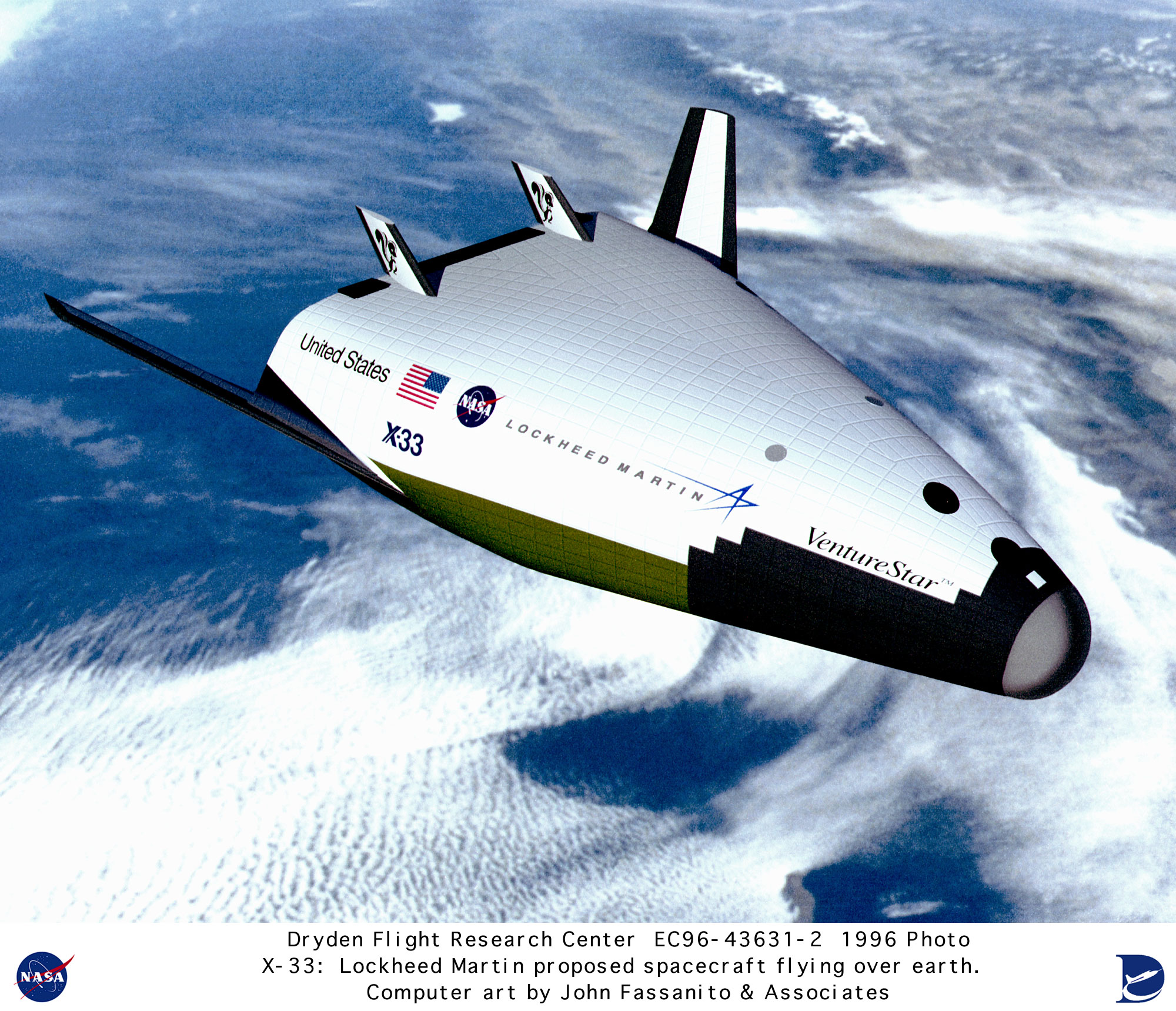
 The original X-33/VentureStar was supposed to look like this:


 But in the later incarnations, it looked like this:


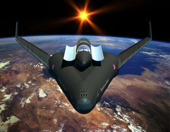
 The added wing size was to move the CP rearward to keep the CG ahead of it. 

 Partitioned propellant tanks are nothing new actually in aerospace. They are quite commonly used on jet airliners to deal with the problem of CG shift as fuel is burned off:

Concorde.
Balancing by Fuel-Pumping.
The Concorde Tank-Schematic:

"1 + 2 + 3 + 4 are the Collector-Tanks, feeding the engines directly. Usually they feed there counterpart engines – but they can be cross-switched to feed more and/or other engines at the same time.
5 + 7 and 8 + 6 are the Main-Transfer Tanks, feeding the 4 Collector-Tanks. Initially 5 + 7 are active. If those are empty 6 + 8 take over (or must be activated from the Engineering Panel!).
5a + 7a are Auxiliary-Tanks (to 5 and 7).
9 + 10 are the Trim-Tanks for balancing forward
11 is the Trim-Tank for balancing afterward"

 Then the partitioned tanks could solve two problems of the dry mass of the X-33/VentureStar: weight growth in the tanks and in the wings.


 Bob Clark

Sunday, June 10, 2018

DARPA's Spaceplane: an X-33 version, Page 2.

Copyright 2018 Robert Clark

 The OldSpace companies had always discounted the viability of reusable launchers on the grounds that the launch market was not enough to pay for it. However, a new market will soon be opening up for hundreds to thousands of launches required for the impending satellite megaconstellations. Now even the OldSpace company ArianeSpace is speaking of transitioning to reusability.

 So with reusability soon to become prevalent we have now further justification for resurrecting the X-33. Boeing supported by a DARPA grant is developing a reusable, spaceplane first stage, the XS-1, then Lockheed with the X-33 would have a competing reusable launcher.

 In the blog post DARPA's Spaceplane:an X-33 version, I discussed that the X-33 used as a reusable first stage has importance beyond that of just a test stage of an operational SSTO, the VentureStar. For the X-33 could be its own operational vehicle, cutting costs in its own right as a reusable first stage.  But intriguingly the problems that originally doomed the X-33 and its SSTO follow-on the VentureStar may also be solvable.

 As discussed in that earlier post, it was the failure of the composite tanks that caused the X-33 program to be cancelled. But some new high strength aluminum alloys may have the comparable lightweight characteristics as carbon composite tanks.

 Carbon composite propellant tanks are a pretty well developed technology, as long as they are cylindrically shaped. But the unusual conformal shape of the composite tanks on the X-33 caused them to fail.

 Carbon composite saves about half-off the weight of standard aluminum tanks. But interestingly some new aluminum alloys have comparable high strength at lightweight as carbon composite and therefore could be used to give the lightweight tanks needed. 

 See for example the graphic:


  The 7075 T6 alloy has nearly twice the strength per weight as the standard 6061 T6 alloy, and the 7068 T6 was nearly 2.5 times better. 

 A consideration as described on that page is that 7075 is 2 to 3 times more expensive than the standard 6061 and the 7068 is 3 to 4 times more expensive. But considering that because of their higher strength, smaller amounts of the material by a factor of 2 to 2.5 would be needed the price difference in practice would not be as great.

 Note also since it was the inability to produce the composite tanks in the X-33 at the needed lightweight that caused the program to be cancelled, existence of the high strength aluminum alloys make the SSTO VentureStar once again viable.

 Development Cost.

 The cost of carbon fiber is about twice that of standard aluminum, so the cost of the tanks with high strength aluminum would not be much more than the cost of the carbon fiber X-33. Since Lockheed would be paying this itself, it might want first to do a smaller version of the X-33.

 In the earlier "DARPA's SpacePlane" post, I suggested a smaller version half-size in linear dimensions of the X-33 might cost ca. $45 million to build. This would test the technology and moreover using it as an upper stage of the X-33 would give a fully reusable system.

   Bob Clark

UPDATE 7/4/2018: 

 I've been informed of other other high strength, lightweight metal alloys that could also allow VentureStar to achieve its goal of a being a reusable SSTO, and allow the X-33 to be able to serve as a low cost reusable first stage.

 The alloys have various strengths and weaknesses. For example some are are just now being experimented with but their measured strength-to-weight ratio is more than 3 times better than standard aluminum. Some are steel alloys which have better weldability than the aluminum alloys, etc.

 For instance in the graphic above, the titanium 6Al-4V alloy is a little better than the 7075 and is already used in rockets for example for solid motor casings.

 There is also a high strength steel alloy, the 17-7 PH stainless steel CH 900:

Re: SpaceX second stage secret sauce?
https://forum.nasaspaceflight.com/index.php?topic=41906.msg1626634#msg1626634

 It has comparable strength-to-weight as the 7068, i.e., nearly 2.5 times better than standard aluminum. It also has better weldability than the aluminum alloys.

 A recent report shows some high strength aluminum alloys such as the 7075 can be 3D-printed:

Engineers Have Found a Way to 3D Print Super Strong Aluminum.
B. Ferguson/HRL Laboratories
by Dom Galeon September 22, 2017 Hard Science
https://futurism.com/engineers-have-found-a-way-to-3d-print-super-strong-aluminum/

 This is useful since the high strength aluminum alloys such as the 7075 have poor weldability. But the conformal shapes of the X-33/VentureStar tanks would be difficult to make without welding.

 Ti 5553 alloy is another ultra strong titanium alloy, even better than the Ti 6Al-4V. It has a max tensile strength in the range of 1,400 MPa. At a density of 4.64 gm/cc, this puts it in strength-to-weight ratio at even better than the 7068 alloy, and nearly 3 times better than standard aluminum:

Processing of a metastable titanium alloy (Ti-5553) by selective laser melting.
November 2016Ain Shams Engineering Journal 8(3)
https://www.researchgate.net/public...nium_alloy_Ti-5553_by_selective_laser_melting

Finally, a titanium alloy known as the Ti185 was long known but it was difficult to produce it so it had uniform strength throughout. A new method of producing it using titanium hydride powder can produce it so it is uniformly strong:

Low-cost and lightweight: Strongest titanium alloy aims at improving vehicle fuel economy and reducing CO2 emissions
April 1, 2016, Pacific Northwest National Laboratory

https://phys.org/news/2016-04-low-cost-lightweight-strongest-titanium-alloy.html

 Approaching 1,700 MPa in tensile strength, it would be 3.5 times better on strength-to-weight than standard aluminum. Because it is made of titanium hydride powder, it may also be possible to make it by 3D-printing, which would solve the problem of producing a conformal shape for the tanks of the X-33/VentureStar.


Tuesday, August 22, 2017

Orbital rockets are now easy, page 2: solid-rockets for cube-sats.


Copyright 2017 Robert Clark

Introduction.
  In the blog post "Orbital rockets are now easy", I argued that with altitude compensation, liquid-fueled orbital rockets become within the capabilities of most university undergraduate labs.

 Here I'll argue solid-fuel rockets can also be built by amateurs to reach orbital space.

 I was impressed by this university teams launch to 144,000 feet of a suborbital solid-fuel rocket:

USC Rocket Propulsion Laboratory Breaks Record.
Amy Blumenthal | March 16, 2017
Student-run RPL launches rocket of own design to 144,000 feet.

LAUNCH OF FATHOM II ON MARCH 4, 2017. AT 144,00 FT FATHOM II WAS THE HIGHEST ALTITUDE FOR A ROCKET ENTIRELY DESIGNED AND MANUFACTURED BY STUDENTS
https://viterbischool.usc.edu/news/2017/03/usc-rocket-propulsion-laboratory-breaks-record/

  However, using essentially "off-the-shelf" components, you can get a 3-stage solid rocket of comparable size to actually reach orbit. Moreover, I was surprised to see after running a launch simulation program that you don't even need altitude compensation to accomplish it.

 By essentially off-the shelf, you could use solid-rocket motors sold to amateurs but with an addition of a lightweight carbon-composite casing that amateurs such as the USC team already have been making themselves for their own rockets.


 You would have Cesaroni Technology, or other solid motor manufacturer, make their motors with only a thin aluminum case, not meant to hold the full combustion chamber pressures. The amateurs would then make the carbon composite case rated for the full combustion chamber pressure.

 Cesaroni also makes commercial sounding rockets with carbon composite casings but this is likely to be more expensive than if the amateurs make it themselves.

Specifications.
 This motor by Cesaroni Technology, or similar motors by other manufacturers, could form the basis of the orbital rocket:


  This motor though only has a mass ratio of about 2.5 to 1, adequate for amateurs doing high power rocketry test flights, but not for an orbital rocket. However, you can save about half of the weight of the aluminum casing used by replacing it by carbon composite.

 Cesaroni was able to do this for the suborbital rocket SpaceLoft they constructed for UP Aerospace, Inc.:

CTI rocket motor successfully powers the launch carrying the ashes of astronaut and James Doohan - April 30, 2007.
On April 28th, a Spaceloft™XL rocket successfully completed a round-trip space flight launched from Spaceport America. This rocket was developed by UP Aerospace Inc. of Hartford, Conn. The rocket carried a wide variety of experiments and payloads, which included the cremated remains of Star Trek's "Scotty", James Doohan and NASA astronaut and pioneer Gordon Cooper. In addition, the cremated remains of more than 200 people from all walks of life were onboard. Also flown into space on the SL-2 Mission were dozens of student experiments from elementary schools to high schools to universities - from across America and worldwide - as well as innovative commercial payloads.
The flight was a successful demonstration of the rocket motor developed and built by Cesaroni Technology Incoporated (CTI). CTI started the design process in September of 2005. CTI specializes in low cost propulsion systems for military and space applications and used its experience to develop an affordable, reliable propulsion system for the rocket. The motor has a carbon fiber composite case and a monolithic solid propellant grain that is bonded to the casing.
Watch the post-launch coverage as carried by local television station KRQE here (9 Mb)
Watch the launch as carried by the BBC here (1 Mb)
Watch pre-launch coverage as carried by CTV Toronto here (9 Mb)
Watch pre-launch coverage as carried by CBC Toronto here (9 Mb)
Technical data for the UPA-264-C rocket motor


 So we'll assume the Cesaroni Pro150 can get a 0.8 propellant fraction by using carbon composite casing. We'll round off the propellant mass to 20 kg, and take the dry mass as 5 kg. We'll take this as the third stage of our rocket.

 For the lower stages, the size of stages commonly are in the range of 3 to 5 times larger than the succeeding stage. We'll take the second stage as 4 times larger than the third stage at a 80 kg propellant weight and 20 kg dry weight. For the first we'll take it as larger by an additional factor of 4 to a 320 kg propellant weight and 80 kg dry weight.

 Now for the specific impulses for the stages. This commercial solid motor has a similar sea level Isp as the Cesaroni solid rocket motor Pro150:

Star 37.
Thiokol solid rocket engine. Total impulse 161,512 kgf-sec. Motor propellant mass fraction 0.899. First flight 1963. Solid propellant rocket stage. Burner II was a launch vehicle upper stage developed by Boeing for the Air Force Space Systems Division. It was the first solid-fuel upper stage with full control and guidance capability developed for general space applications.
AKA: Burner 2;TE-M-364-1. Status: First flight 1963. Number: 180 . Thrust: 43.50 kN (9,779 lbf). Gross mass: 621 kg (1,369 lb). Unfuelled mass: 63 kg (138 lb). Specific impulse: 260 s. Specific impulse sea level: 220 s. Burn time: 42 s. Height: 0.84 m (2.75 ft). Diameter: 0.66 m (2.16 ft).
Thrust (sl): 33.600 kN (7,554 lbf). Thrust (sl): 3,428 kgf.
http://www.astronautix.com/s/star37.html

 So we'll estimate the vacuum Isp of the Cesaroni Pro150 to be in the Star 37's range of 260 s. However, rocket stages can get higher vacuum Isp's by using longer nozzles. A 285 s Isp is not uncommon for solid rockets motors with vacuum optimized nozzles, such as the Star 48.

 So we'll take the Isp for the second and third stage as 285 s.

 For the thrust, we'll take the thrust of the third stage as the same as the Pro150 of 8 N, and assume the thrust for the second and first stage scale according to their size so to 32 N and 128 N, respectively.

 Now use Dr. John Schilling's launch performance calculator to estimate the payload.

 The input page looks like this:


 Note there some quirks of this program you need to be aware of if you use it. First, always use the vacuum values for the Isp's and thrust numbers, since the program already takes into account the diminution at sea level. Second, always set the "Restartable Upper Stage" option to "No", rather than the default "Yes", otherwise the payload will be reduced. Third, always set the launch inclination to match the launch site latitude, otherwise the payload will be reduced. This is related to the fact that changing the orbital plane involves a delta-v cost. So for the Cape Canaveral launch site, the launch inclination should be set to 28.5 degrees.

Now, here's the result:


 So a payload to LEO of 7 kg. And this with standard nozzles, no altitude compensation required.

Structure.
  To save costs, I'm envisioning making the components as much "off-the-shelf" as possible. But among its standard products Cesaroni offers the Pro150 as the largest motor. So to get the larger second and first stages, we would have to combine multiple copies of this motor.

  I could cluster them in parallel, but for the first stage that would be 16 of them, and you would have the problem of simultaneous ignition with that many motors.

  So what I'm envisioning is take 4 copies of the Pro150 stacked vertically one on top of the other for the second stage, then cluster 4 of these second stage motors in parallel for the first stage.

 The question is though about the vertical stacking is how much the thrust scales in this case. If for the solid motors the propellant burned from the bottom upwards, then the thrust would be the same as for a single motor, you would just get 4 times longer burn time.

  But that's not how large solid motors work. Actually, they have a hollow region in the center so the propellant burns from the inside surface, proceeding outwards. In this case, you have a greater amount of propellant being burned per second because of the larger vertical surface area with the stacked segments. In fact, the thrust scales linearly with the number of segments.

 By the way, the reason why I don't just also stack the first stage vertically, is because of the thinness of the rocket that would result. The Pro150 is about 3 feet long and 1/2 foot wide. If you stacked vertically 16 for the first stage, 4 for the second, and 1 for the third, that would be a rocket 63 feet high but only 1/2 foot wide, for a ratio of length to width of over 120 to 1.

 This ratio of length to width is called the "fineness ratio". Rocket engineers don't like for it to be higher than about 20 to 1 because of the severe bending loads that would result. The upgraded version of the Falcon 9 has been noted for its long, skinny profile, and has a fineness ratio of about 20 to 1. The Scout solid rocket had a fineness ratio of about 24 to 1. Solid rockets can support a higher fineness ratio because their thicker walls can withstand higher loads. Still, 120 to 1 would very likely be too high.

  So to avoid this I decided to form the first stage by clustering in parallel four copies of the second stage. Note here these four clustered motors arranged around the second stage will provide the full thrust for the first stage while the central second stage motor will not fire until the four clustered motors are jettisoned.

 It would be possible though to get a single vertically stacked motor using multiple segments if the segments were shorter, resulting in a smaller rocket. For instance, there is a market for cubesats at only 1 kg mass to orbit. If you made the solid motor segments only about 1/2 foot long by cutting the Pro150 into 6 segments, you could take one of these smaller segments as the third stage, 4 segments for the second stage, and 16 segments for the third stage.

Cost.
 The Cesaroni Pro150 retails for about $3,000 and in general the Cesaroni solids cost in the range of $100 per kg of the motor mass:

Cesaroni O8000 White Thunder Rocket Motor.   
$3,099.95
Product Information
Specification
Brandname:  Pro150 40960O8000-P                  Manufacturer:  Cesaroni Technology
Man. Designation:  40960O8000-P                    CAR Designation:  40960 O8000-P
Test Date:  4/10/2008                                   
Single-Use/Reload/Hybrid:  Reloadable             Motor Dimensions mm:  161.00 x 957.00 mm (6.34 x 37.68 in)
Loaded Weight:  32672.00 g (1143.52 oz)         Total Impulse:  40960.00 Ns (9216.00 lb/s)
Propellant Weight:  18610.00 g (651.35 oz)       Maximum Thrust:  8605.10 N (1936.15 lb)
Burnout Weight:  13478.00 g (471.73 oz)          Avg Thrust:  8034.50 N (1807.76 lb)
Delays Tested:  Plugged                                      ISP:  224.40 s
Samples per second:  1000                                  Burntime:  5.12 s
https://www.csrocketry.com/rocket-motors/cesaroni/motors/pro-150/4g-40kns-reloads/cesaroni-o8000-white-thunder-rocket-motor.html

 So take the cost of the third stage, derived from the Cesaroni Pro1050, as $3,000, and the second stage 4 times larger as $12,000, and the first stage larger by an additional factor of 4 as $48,000. So $63,000 for a smallsat launcher with a 7 kg payload to orbit.

Applications.
 Several universities have created their cubesats and smallsats to be launched piggyback on large rockets such as the Falcon 9. However, the solid rocket launcher formed from essentially off the shelf components could be built by any interested university itself thus creating their own launcher and satellite.

 Despite the small size of such satellites, and their low construction cost, the launch cost is still not cheap when sent piggyback. SpaceX for their latest incarnation of the Falcon 9 is charging about $60 million for a 20,000 kg payload to LEO, about $3,000 per kilo. But the price is much higher than that for small payloads that have to ride piggyback on launchers. For instance Spaceflight Industries charges about $100,000 per kilo to book such flights. But a 1 kg cubesat launch would only cost in range of $9,000 for one of these dedicated solid-rocket launchers.

 The remaining entrants to the Google Lunar X-Prize will have to pay expensive launch costs for their spacecraft to the Moon. But with the university teams using their own solid rocket launchers, the launch costs would be so cheap the teams could afford to make many attempts to win the lucrative $30 million prize to soft-land on the Moon, and many more teams could have remained in the race.

 Also, both DARPA and the Army funded programs to develop such small dedicated launchers (liquid fueled), with their ALASA and SWORDS programs. But both their programs failed. They wanted to get about 25kg to 50kg to orbit for a launch cost of $1,000,000, about $20,000 to $40,000 per kilo. But the small size solid rockets will be able to beat this price, moreover will be more operationally responsive by using solid rockets. In a follow up post I'll discuss the payload can be more than doubled by using altitude compensation reducing the per kilo cost even further.


National security implications.
 Recently, there has been some discussion on creating Ultra Low Cost Access to Space (ULCATS). See for instance this study:

FAST SPACE: LEVERAGING ULTRA LOW-COST SPACE ACCESS FOR 21ST CENTURY CHALLENGES.
http://www.airuniversity.af.mil/Portals/10/Research/documents/Space/Fast%20Space_Public_2017.pdf

 Most of the discussion has been about how this would improve U.S. capabilities. But surprisingly little has been about what are the national security implications of any university world-wide and many knowledgeable amateur groups world-wide launching their own rockets to orbit.

 To prepare for this, which will be here like tomorrow, this discussion must begin now.


    Bob Clark

Note: thanks to former aerospace engineer and math professor GW Johnson for helpful discussion on this topic on the NewMars.com forum:

Amateur solid-fueled rockets to *orbital* space?
http://newmars.com/forums/viewtopic.php?id=7763


Thursday, August 13, 2015

Orbital rockets are now easy.

Copyright 2015 Robert Clark


Falcon 1 Upper Stage Based Orbital Launcher.
 In the blog post "On the lasting importance of the SpaceX accomplishment" I suggested that SpaceX's low cost, commercial approach to developing the Falcon 9 will lead to this being emulated by other launch providers and then, eventually, to spaceflight becoming routine. However, ironically, it might turn out their simplest development and one they dispensed with will have the fastest effect towards making orbital access routine.

  It's the Falcon 1 upper stage. Compared to the first stage and certainly compared to the Falcon 9, it's a rather simple stage only using a pressure-fed engine, the Kestrel


Kestrel engine

  Pressure-fed engines and stages are much easier to develop than pump-fed ones. For instance there are the rockets developed by Armadillo AerospaceMasten Space Systems, and Garvey Spacecraft Corporation

 And this was also the case for the Project Morpheus lunar lander stage. In the blog post "The Morpheus lunar lander as a manned lander for the Moon", I discussed the NASA's Project Morpheus emulating a low-cost commercial space approach was able to develop two Morpheus landers for only $14 million. And actually the parts only costs were in the range of $750,000 per lander.

 The construction costs for pressure-fed engines can also be low cost. For instance Project Morpheus was able to produce their engines at a cost of only $60,000:

NASA dreams of future Morpheus project templates.
March 14, 2015 by Chris Bergin
The main engine – which was also tested at the Stennis Space Center – could throttle at a ratio of 4 to 1, ranging between 1,400 and 5,400 pounds thrust. All Morpheus engines were custom designed and built specifically for Morpheus and only cost $60,000 each.

 The specifications for the Falcon 1 upper stage are given here:

Falcon 1.

 It has a 360 kg dry mass and 3,385 kg propellant mass, and a 3,175 kilogram-force vacuum thrust and 327 s vacuum Isp using the Kestrel engine. This is an upper stage engine however with a long nozzle that can't be used at sea level. In the post "Altitude compensation attachments for standard rocket engines, and applications" I described various attachments to be made to existing engines to give them altitude compensation ability. 

 However, since pressure-fed engines are so comparatively low-cost they could be designed from the beginning to have aerospike nozzles. There is for instance the aerospike engine of Garvey Spacecraft. And Firefly Space Systems  will construct an aerospike nozzle by using numerous small engines arranged around a central spike.

 The question though is how much thrust could be developed with the Kestrels at sea level using altitude compensation. I'll estimate from the formula for Isp for a rocket engine:

The ideal exhaust velocity is given by

where k is the specific heat ratio, R* is the universal gas constant (8,314.4621 J/kmol-K in SI units, or 49,720 ft-lb/(slug-mol)-oR in U.S. units), Tc is the combustion temperature, Mis the average molecular weight of the exhaust gases, Pc is the combustion chamber pressure, and Pe is the pressure at the nozzle exit.
http://www.braeunig.us/space/propuls.htm#Isp


 The pressure factor at the end reduces the Isp at sea level. The specific heat ratio k is about 1.24 for kerolox. The Kestrel operates at a chamber pressure of 135 psi. Then the pressure factor is:
sqrt(1-(14.7/135)^(.24/1.24)) =  .591. So the Isp at sea level is 327*.591 = 193 s and the sea level thrust is .591*3,175 = 1,876 kilogram-force. 

 Note for this estimate to be valid you have to have altitude compensation so that the engine has optimal performance at sea level, i.e., you don't have the back-pressure loss that results from non-optimal expansion.

 Because of the 3,745 kg gross mass of the stage though, we need to reduce the propellant load to be loftable by the single Kestrel at the 1,876 kilogram-force sea level thrust. We'll reduce the propellant load by a factor of .45, so to .45*3,385 = 1,520 kg. We want also to maintain the relatively high mass ratio for the stage so we'll reduce the tank size. The tank mass is proportional to the propellant mass. Subtracting off the 52 kg mass of the Kestrel leaves us 308 kg in the stage dry mass. Multiplying this by .45 gives .45*308 = 138.6 kg. Adding on the 52 kg mass of the Kestrel gives a dry mass of 190 kg. 

 Other elements of a rocket stage such as the insulation, wiring, avionics do not scale linearly with propellant mass as does tank mass. However, since for pressure-fed stages the dry mass is so dominated by the tank mass this gives an approximate value of the stage mass when you scale down the stage size. 

 Moreover we can further reduce the dry mass by using composite propellant tanks. Microcosm, Inc. is making small-sized composite tanks that could be used for the purpose. NASA research has shown composite tanks can save 30% off the mass of aluminum-lithium tanks. Since Al-Li tanks save about 25% off the weight of standard aluminum tanks, this means composites can save about 50% off the weight of standard aluminum propellant tanks. 

 To estimate the mass this could save for this application, historically the propellant mass to tank mass ratio for kerolox for standard aluminum tanks is about 100 to 1. Note though this is for pump-fed engines that only need their stages at about 2 bar, about 30 psi. When the tank pressure is increased for pressure-fed engines the tank mass is correspondingly increased. The Falcon 1 upper stage tanks are kept at 200 psi pressure. So for our propellant mass of 1,520 kg, the tank mass assuming standard aluminum might be (1,520 kg/100)*(200 psi/30 psi) = 101 kg. Then a  reduction of 50% in the tank mass would cut 50 kg from the dry mass to bring it to 140 kg. However, we'll calculate here the payload using 190 kg dry mass number, as the dry mass here is approximate since some components of the stage won't actually scale proportionally with the stage size.

Cross-Feed Fueling for Multiple Cores.
 To increase payload we'll use cross-feed fueling. Note that cross-feed fueling is actually a well-understood technology, having been used on the Space Shuttle OMS engines:

Propellant Storage and Distribution.
"The propellant storage and distribution system consists of one fuel tank and one oxidizer tank in each pod. It also contains propellant feed lines, interconnect lines, isolation valves and crossfeed valves.
"The OMS propellant tanks of both pods enable the orbiter to reach a 1,000-foot- per-second velocity change with a 65,000-pound payload in the payload bay. An OMS pod crossfeed line allows the propellants in the pods to be used to operate either OMS engine."

 And it has also been used for decades for jet airliners:

Concorde.
Balancing by Fuel-Pumping.
The Concorde Tank-Schematic:

"1 + 2 + 3 + 4 are the Collector-Tanks, feeding the engines directly. Usually they feed there counterpart engines – but they can be cross-switched to feed more and/or other engines at the same time.
5 + 7 and 8 + 6 are the Main-Transfer Tanks, feeding the 4 Collector-Tanks. Initially 5 + 7 are active. If those are empty 6 + 8 take over (or must be activated from the Engineering Panel!).
5a + 7a are Auxiliary-Tanks (to 5 and 7).
9 + 10 are the Trim-Tanks for balancing forward
11 is the Trim-Tank for balancing afterward"

 To emulate rocket cross-feed fueling with the Schilling Launch Performance Calculator, note that during the parallel burn portion of the flight the propellant for the center core engines is coming from the side booster stage(s). This ensures that the center core will have a full propellant load during its solo burn portion of the flight, after the side booster(s) are jettisoned. 

 So the total amount of propellant burned during the parallel burn portion is that of the side booster(s) only. But the Schilling Calculator assumes the amount of propellant burned in the center core during the parallel burn is the same as the amount burned in each side booster. So enter in the Calculator for the booster propellant load a fraction of the actual propellant load of a core equal to the number of side boosters divided by the number of cores. So if you're using 2 cores with one used as a side booster enter in the Calculator booster column 1/2 the amount of the actual core propellant load. And if using 3 cores with 2 used as side boosters, enter in 2/3rds the actual core propellant load in the booster section. This will ensure the Calculator interprets the total propellant burned during the parallel burn portion is that of the actual side booster(s) only.

 But you also want the Calculator to take the amount of propellant burned during the center core's solo burn portion of the flight as that of a full propellant load. Since it is already taking it to have burned the same amount as what the side boosters have burned during the parallel burn portion, add this amount onto the actual propellant load of a core and enter this into a first stage column of the Calculator. For the other specifications for both booster(s) and center core such as Isp, dry mass, and thrust enter in the actual values.

 We'll calculate here the case for using two side booster of same size as the central core. Enter in the Schilling calculator the dry mass of 190 kg for the boosters and the first stage, which is the central core. For the thrust and Isp for the boosters and the first stage, enter in the vacuum Isp of 327 s and vacuum thrust of 31.1 kN in the calculator. However, to emulate cross-field fueling, for the propellant fields enter in (2/3)*1,520 kg = 1,013 kg in the booster section and 1,013 kg + 1,520 kg = 2,533 kg in the first stage section. Choose Cape Canaveral as the launch site and 28.5 degrees as the launch inclination to match the latitude for the launch site. For the "Restartable Upper Stage" select "No", otherwise the payload will be reduced. Then the calculator gives the result:

Mission Performance:
Launch Vehicle:  User-Defined Launch Vehicle
Launch Site:  Cape Canaveral / KSC
Destination Orbit:  185 x 185 km, 28 deg
Estimated Payload:  63 kg
95% Confidence Interval:  19 - 116 kg

"Payload" refers to complete payload system weight, including any necessary payload attachment fittings or multiple payload adapters
This is an estimate based on the best publicly-available engineering and performance data, and should not be used for detailed mission planning. Operational constraints may reduce performance or preclude this mission.


 We could get over 100 kg if we used three side cores. 

Methane for Improved Performance.
 We could also increase the payload using methane instead of kerosene as the fuel. For booster stages, methane has about the same performance as kerosene since the greater density for kerosene makes up for its lower Isp. But for upper stages methane offers better performance since it would give a lighter stage that had to be lofted by the lower stages. So if you wanted to use identical stages for simplicity and cost, methane would be the preferred fuel.

 There is also a key practical reason why methane might be preferred. NASA has developed the methane-fueled engine for the Morpheus rocket stage. With NASA's Technology Transfer program the technical info on the engine would also be shared at least for American companies. Then you would only have to pay the ca. $60,000 construction costs for the engine. 

 Considering that both the Kestrel and Morpheus engines are reusable this already low cost launcher can cut the cost to space considerably. It then could be used for DARPA's proposed reusable launchers discussed here: "NASA Technology Transfer for suborbital and air-launched orbital launchers." In an upcoming blog post I'll also show that using a single one of these cores, it can be used as either the reusable first stage booster, or the air-launched orbital stage for these DARPA programs.

Scale-up to Large Launchers. 
 Note this is a 5,130 gross mass launcher to launch a 63 kg payload. Pressure-fed stages scale up more easily than pump-fed ones since you don't have the complexity of creating a turbopump for the larger size engines. The Mercury spacecraft that carried John Glenn massed 1,300 kg. Using modern materials we could probably make a one-man capsule for 500 kg. Then we would only have to scale up our 3 core launcher by a factor of 8 to launch a one-man capsule to orbit. This would be a 41,000 kg gross mass launcher compared to the 120,000 kg gross mass Atlas rocket that launched John Glenn to space.

  Bob Clark


Thursday, January 15, 2015

NASA Technology Transfer for suborbital and air-launched orbital launchers.

Copyright 2015 Robert Clark

 I have become enamored of NASA's Morpheus lunar lander project. In the post "NASA Technology Transfer for manned BEO spaceflight", I discussed how it can be used to produce a manned lunar lander, or asteroidal lander, for a few 10's of millions of dollars, far less than the $10 billion estimated to be needed by NASA. And in "NASA Technology Transfer for Orbital Launchers", I discussed how its engines could be used for the small orbital launch system Firefly, resulting in a significant reduction in the launcher's development costs.

 I don't think NASA fully appreciates the usefulness of the Morpheus development. Here I'll show how the Morpheus itself can be used to produce suborbital launchers, and also the stages for orbital launchers. For instance the Morpheus can be used to provide the solution to DARPA's ALASA air launched, small orbital system.

 The Wikipedia page on the Morpheus gives its propellant load as 2.9 metric tons (mT) and dry mass as 1.1 mT. Its methane/LOX engine has an Isp of 321 s with a thrust of 24 kN, 2,450 kilogram-force (kgf).


 Note this means when fully fueled the single engine could not lift the vehicle in Earth's gravity. The single engine of course would be fine for its intended purpose as a lunar lander at 1/6th gravity. However, for a Earth launch system we'll use a half-size vehicle to be launchable with a single engine. Rounding off this gives it a propellant mass of 1.5 mT and dry mass of .5 mT. Compared to the full Morpheus this will have only two spherical propellant tanks instead of four, one each for the liquid methane and LOX.

 Since this will be reaching high velocity through Earth's atmosphere it will have to be streamlined. Then we'll place the two propellant tanks inline vertically. We'll also need an aeroshell. To save weight we could make the aeroshell composite. Another possibility would be to make the aeroshell inflatable. Since the aeroshell would not need to be load-bearing and with the possibility to make it inflatable we'll assume it adds only a small proportion to the weight. We could save additionally weight by making the tanks out of aluminum-lithium alloy, titanium, or composites. Alternatively, we could use a cylindrical tank to hold the propellants to eliminate the need for an aeroshell.

 Suborbital Case.

 This page gives the required delta-v for a suborbital flight as in the range of ca. 2,400 m/s:

Flight Mechanics of Manned Sub-Orbital Reusable Launch Vehicles with Recommendations for Launch and Recovery.
Mechanical and Aeronautical Engineering Department, University of California, Davis, CA 95616-5294
Marti Sarigul-Klijn Ph.D. and Nesrin Sarigul-Klijn*, Ph.D.
An approximate delta V to reach 100 km is 7,000 to 8,000 fps (2,100 to 2,400 m/s) for vertical takeoff, with slightly less delta V needed for air launch, and significantly more required for horizontal takeoff.
http://www.spacefuture.com/archive/flight_mechanics_of_manned_suborbital_reusable_launch_vehicles_with_recommendations_for_launch_and_recovery.shtml

  Now, at a 1.5 mT propellant load, .5 mT dry mass, .25 mT payload, and 321 s Isp, the vehicle can do a delta-v of 321*9.81ln(1 + 1.5/(.5 + .25)) = 3,460 m/s, sufficient for a suborbital flight.

 There are commercial opportunities for suborbital flight with NASA. Also using two to four copies or scaled up that many times this could also be used for a suborbital tourism vehicle.

DARPA Air-Launched Orbital Vehicle.

 DARPA is funding research into a small air-launched system called ALASA, As described in the blog post "Dave Masten's DARPA Spaceplane, page 2: an Air Launched System", high altitude supersonic air-launch at Mach 2 can cut 1,600 m/s from the delta-v needed for low Earth orbit. This would reduce the delta-v that needed to be supplied by the rocket from 9,100 m/s to 7,500 m/s.

 We'll use two copies of the half-size Morpheus firing in parallel and cross-feed fueling. Cross-feed fueling allows the upper stage to have its full level of fuel after staging, unlike the usual case with parallel staging. As in the earlier blog post, we'll again use the Star 17 solid stage as the final, orbital stage:

Encyclopedia Astronautica.
Star 17
Solid propellant rocket stage. Loaded/empty mass 124/14 kg. Thrust 19.60 kN. Vacuum specific impulse 280 seconds.
Cost $ : 0.580 million.
Status: Out of production.
Gross mass: 124 kg (273 lb).
Unfuelled mass: 14 kg (30 lb).
Height: 0.98 m (3.21 ft).
Diameter: 0.44 m (1.44 ft).
Span: 0.44 m (1.44 ft).
Thrust: 19.60 kN (4,406 lbf).
Specific impulse: 280 s.
Specific impulse sea level: 220 s.
Burn time: 18 s.
Number: 25 .
http://www.astronautix.com/stages/star17.htm

 Then we can get a payload of 55 kg to orbit by supersonic air-launch:

321*9.81ln(1 + 1.5/(.5 + 2.0 + .124 + .055)) + 321*9,81ln(1 + 1.5/(.5 + .124 + .055)) + 280*9.81ln(1 + .110/(.014 + .055)) = 7,690 m/s.


  Bob Clark


Could Blue Origin develop a lander for Artemis III?

Copyright 2025 Robert Clark SpaceX is coming under increasing criticism for its delay in developing the Starship lunar lander: U.S. Is Losin...