Showing posts with label graphene. Show all posts

Thursday, February 2, 2023

Creating arbitrarily long graphene and carbon nanotubes. 2nd UPDATE: 2/24/2023: additional proposals for lengthened graphene-nanotube hybrids.

 Copyright 2023 Robert Clark

(patents pending)

(Appended at the bottom below are additional suggestions for combining graphene/carbon nanotubes.)

 Carbon nanotubes were created in the early 1990's. Experiments on them revealed extraordinary strength in the range of 1,000 times higher tensile strength per weight than standard grade steel plate and 100 times higher tensile strength per weight than the strongest steel wires available. 

 Graphene which can be regarded as carbon nanotubes flattened out were discovered about a decade later. Experiments confirmed they had comparable strength to carbon nanotubes.

 The only problem towards making them common industrial materials is that they have only been available in small sizes, at microns to a few millimeters in size.

 This is a proposal for constructing larger size graphene and carbon nanotubes. 

I.)Creating Large Graphene Sheets.

Recent research has produced hybrids of graphene and carbon nanotubes:

James’ bond: A graphene/nanotube hybrid

Rice University’s James Tour Group creates single-surface material for energy storage, electronics
Graphic

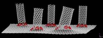
Seven-atom rings (in red) at the transition from graphene to nanotube make this new hybrid material a seamless conductor. The hybrid may be the best electrode interface material possible for many energy storage and electronics applications. Image by Yang Yang/Yakobson Group

Graphic

Nanotubes are grown from graphene to create nanoscale odako, so named for the giant Japanese kites they resemble. Image courtesy of the Tour Group


https://news2.rice.edu/2012/11/27/james-bond-a-graphenenanotube-hybrid-2/


 The researchers were able to attach carbon nanotubes to graphene sheets. 


Several teams have been able to create such hybrids, [1], [2], [3], [4], [5]. Usually, these are formed by placing nanotubes onto graphene. However, one team was able to place graphene onto nanotube surfaces, [6].


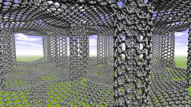
 Repeating such hybrids into multiple layers, the strength and electrical properties of graphene and carbon nanotubes can be extended into 3-dimensions, [7], [8], [9], [10]:


Hybrid Structures of Graphene and Nanotubes Exhibit Unique Mechanical Properties

Carbon nanotube pillars between sheets of graphene may create hybrid structures with a unique balance of strength, toughness and ductility throughout all three dimensions, according to Rice University scientists. Five, seven or eight-atom rings at the junctions can force the graphene to wrinkle. Illustration by Shuo Zhao and Lei Tao
https://www.azonano.com/news.aspx?newsID=33709


 However, other research had shown it is possible to "unzip" carbon nanotubes to turn them into graphene sheets:


Unzipping Carbon Nanotubes: A Peeling Method for the Formation of Graphene Nanoribbons†

First published: 19 August 2009
 Graphical Abstract

Zipper examined: Elegant unzipping procedures result in the clean opening of multiwalled carbon nanotubes, leading to graphene nanoribbons (see scheme). Since graphene exhibits outstanding electronic properties, this method may be important in the development of modern nanoelectronic applications.

Description unavailable

https://onlinelibrary.wiley.com/doi/full/10.1002/anie.200902534?saml_referrer

 Several different methods have been found for accomplishing the unzipping, [11], [12], [13]. However, for my purposes the unzipping has to be targeted, as well as being able to cut the graphene at a targeted location in the graphene/nanotube hybrid. I therefore suggest using electron beams or x-ray beams to cut the graphene/carbon nanotubes at the specified locations:


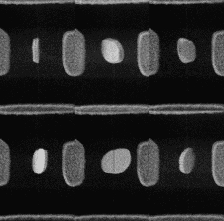
 The idea would be to slice the graphene-nanotube along the lines shown then open up the material flat, to get a larger single sheet of graphene. Then the process would be repeated to attach further nanotubes, slice them open as well and open them up to get a larger sheet of graphene to make a graphene sheet arbitrarily large.

II.)Creating long nanotubes.

That's for creating arbitrarily large graphene. How about for arbitrarily long nanotubes? First the large graphene sheets would be created. Then methods for rolling up the graphene into carbon nanotubes would be used. Theoretical simulations had shown this possible, [14]:

Graphene Nanoribbons Zip Up
February 23, 2012• Physics 5, s29
Nanoscale planar materials such as graphene could be twisted to fabricate tubular objects.
O. Kit, Phys. Rev. B (2012)
https://physics.aps.org/articles/v5/s29


Figure caption
O. Kit, Phys. Rev. B (2012)


   And this has been experimentally confirmed:

 2013 Oct 4; 4: 2548.
Published online 2013 Oct 4. doi: 10.1038/ncomms3548
Growth of carbon nanotubes via twisted graphene nanoribbons


REFERENCES.

1.)Graphene as an atomically thin interface for growth of vertically aligned carbon nanotubes.
Rahul Rao, Gugang Chen, Leela Mohana Reddy Arava, Kaushik Kalaga, Masahiro Ishigami, Tony F. Heinz, Pulickel M. Ajayan & Avetik R. Harutyunyan 
Scientific Reports volume 3, Article number: 1891 (2013)
https://www.nature.com/articles/srep01891

2.)Growing Carbon Nanotubes from Both Sides of Graphene.
Jinlong Jiang*‡§, Yilun Li‡, Caitian Gao‡#, Nam Dong Kim‡, Xiujun Fan‡, Gunuk Wang‡, Zhiwei Peng‡, Robert H. Hauge‡⊥, and James M. Tour*‡⊥||
ACS Appl. Mater. Interfaces 2016, 8, 11, 7356–7362
Publication Date:February 23, 2016
https://doi.org/10.1021/acsami.5b12254


3.)A Three-Dimensional Carbon Nanotube/Graphene Sandwich and Its Application as Electrode in Supercapacitors.
Zhuangjun Fan, Jun Yan, Linjie Zhi, Qiang Zhang, Tong Wei, Jing Feng, Milin Zhang, Weizhong Qian, Fei Wei
First published: 20 August 2010
https://doi.org/10.1002/adma.201001029

4.)Article
Open Access
Published: 11 March 2019
High-Electrical-Conductivity Multilayer Graphene Formed by Layer Exchange with Controlled Thickness and Interlayer.
Hiromasa Murata, Yoshiki Nakajima, Noriyuki Saitoh, Noriko Yoshizawa, Takashi Suemasu & Kaoru Toko 
Scientific Reports volume 9, Article number: 4068 (2019)
https://www.nature.com/articles/s41598-019-40547-0
5.)A seamless three-dimensional carbon nanotube graphene hybrid material
Yu Zhu, Lei Li, Chenguang Zhang, Gilberto Casillas, Zhengzong Sun, Zheng Yan, Gedeng Ruan, Zhiwei Peng, Abdul-Rahman O. Raji, Carter Kittrell, Robert H. Hauge & James M. Tour 
Nature Communications volume 3, Article number: 1225 (2012)

6.)Open Access
Published: 05 August 2013
Self-Assembly of Graphene on Carbon Nanotube Surfaces.
Kaiyuan Li, Gyula Eres, Jane Howe, Yen-Jun Chuang, Xufan Li, Zhanjun Gu, Litong Zhang, Sishen Xie & Zhengwei Pan 
Scientific Reports volume 3, Article number: 2353 (2013)

7.)AUGUST 2, 2018
Nanotube 'rebar' makes graphene twice as tough
by Mike Williams, Rice University
https://phys.org/news/2018-08-nanotube-rebar-graphene-tough.html
8.)Rebar Graphene
Zheng Yan†, Zhiwei Peng†, Gilberto Casillas∥, Jian Lin‡§, Changsheng Xiang†, Haiqing Zhou†, Yang Yang†‡, Gedeng Ruan†, Abdul-Rahman O. Raji†, Errol L. G. Samuel†, Robert H. Hauge†‡⊥, Miguel Jose Yacaman∥, and James M. Tour†‡§*
ACS Nano 2014, 8, 5, 5061–5068
Publication Date:April 2, 2014
https://doi.org/10.1021/nn501132n

9.)Pillared graphene gains strength
MIKE WILLIAMS – SEPTEMBER 14, 2015
POSTED IN: CURRENT NEWS
https://news2.rice.edu/2015/09/14/pillared-graphene-gains-strength/

10.)Graphene and Carbon Nanotubes: Two Great Materials Even Better Together Researchers use carbon nanotubes to create a reinforced version of graphene.
DEXTER JOHNSON
09 APR 2014
https://spectrum.ieee.org/graphene-and-carbon-nanotubes-two-great-materials-even-better-together


11.)Published: 24 April 2009
Graphene nanoribbons
Unzipping nanotubes
Gavin Armstrong 
Nature Chemistry (2009)
Two methods for producing graphene nanoribbons by unzipping carbon nanotubes have been developed.
https://www.nature.com/articles/nchem.236

12.)Published: 16 April 2009
Longitudinal unzipping of carbon nanotubes to form graphene nanoribbons
Dmitry V. Kosynkin, Amanda L. Higginbotham, Alexander Sinitskii, Jay R. Lomeda, Ayrat Dimiev, B. Katherine Price & James M. Tour 
Nature volume 458, pages872–876 (2009)
https://www.nature.com/articles/nature07872

13.)Unzipping of Single-Walled Carbon Nanotube for the Development of Electrocatalytically Active Hybrid Catalyst of Graphitic Carbon and Pd Nanoparticles.
Siniya Mondal, Sourov Ghosh, and C. Retna Raj
ACS Omega 2018, 3, 1, 622–630
Publication Date:January 19, 2018
https://doi.org/10.1021/acsomega.7b01913

14.)Twisting graphene nanoribbons into carbon nanotubes
O. O. Kit, T. Tallinen, L. Mahadevan, J. Timonen, and P. Koskinen
Phys. Rev. B 85, 085428 – Published 23 February 2012
https://journals.aps.org/prb/abstract/10.1103/PhysRevB.85.085428

UPDATE: 2/14/2023: Squashed together carbon nanotubes and graphene sheets.

(patents pending)  
 A recent report demonstrated producing graphene sheets from squashing carbon nanotubes under diamond anvils:

EDITORIAL FEATURE
New Research Narrows the Gap for Graphene Nanoribbon Applications
Cvetelin Vasilev, Ph.D.
https://www.azonano.com/article.aspx?ArticleID=5868

Article
Published: 06 September 2021
Sub-10-nm graphene nanoribbons with atomically smooth edges from squashed carbon nanotubes.
Changxin Chen, Yu Lin, Wu Zhou, Ming Gong, Zhuoyang He, Fangyuan Shi, Xinyue Li, Justin Zachary Wu, Kai Tak Lam, Jian Nong Wang, Fan Yang, Qiaoshi Zeng, Jing Guo, Wenpei Gao, Jian-Min Zuo, Jie Liu, Guosong Hong, Alexander L. Antaris, Meng-Chang Lin, Wendy L. Mao & Hongjie Dai 
Nature Electronics volume 4, pages 653–663 (2021)
https://www.nature.com/articles/s41928-021-00633-6 (behind paywall)
Free PDF: http://sscms.hpstar.ac.cn/hpstar/upload/files/2021/9/76740ddde9b92399.pdf 
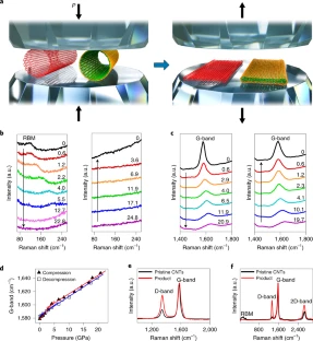


 Then the proposal is to use graphene sheets and/or carbon nanotubes laid one on top of another but with only for a short overlap distance compared to their lengths. The test is to see if the high pressure compression can induce the carbon-carbon bonds of graphene/nanotubes between the layers of the graphene/nanotubes. Previous work with graphene and nanotubes have been able to induce much weaker van der Waals bonds between the carbon atoms. These do not have the same strength as the carbon-carbon covalent bonds that prevail in graphene and carbon nanotubes.


 The purpose of the short overlap distance compared to their lengths is that likely there will be a combination of the stronger carbon-carbon bonds and van der Waals bonds between the layers. You might then need several layers to make the equivalent cross-sectional strength of a single graphene/nanotube layer. However, by making this portion of the composite small compared to the rest of the graphene/nanotubes the overall strength to weight ratio will be close to that of the pure graphene or carbon nanotubes.


2nd UPDATE, 2/24/2023: Cyclic graphene growing nanotubes growing graphene.

(patent pending)

 Above was first described methods of growing carbon nanotubes on graphene, as references, [1], [2], [3], [4], [5]. However, reference [6] described growing graphene on nanotubes:

Open Access
Published: 05 August 2013
Self-Assembly of Graphene on Carbon Nanotube Surfaces.
Kaiyuan Li, Gyula Eres, Jane Howe, Yen-Jun Chuang, Xufan Li, Zhanjun Gu, Litong Zhang, Sishen Xie & Zhengwei Pan 
Scientific Reports volume 3, Article number: 2353 (2013)

  Then the proposal is to cycle repetitively first of growing nanotubes onto graphene and then growing graphene onto nanotubes to produce arbitrarily large graphene-nanotube hybrids.


Saturday, January 25, 2020

Introducing the mechanical rocket motor.I:rotational carbon nanotube propulsion.

Copyright 2020 Robert Clark
(patents pending)

 SpinLaunch has been funded to launch rockets to space electromagnetically from the ground:

Stealth space startup SpinLaunch snares another $35 million from investors.
By Mike Wall
The company's total investment haul is now $80 million.
https://www.space.com/spinlaunch-launch-startup-investment-funding.html

 Though some launch proposals for slinging rockets to space have proposed nearly getting to the full orbital velocity of 7,400 m/s, this proposal seems more modest in proposing getting in the range of 1,500 m/s. The rest of orbital velocity would be provided by onboard rockets.

 However, it may be possible to get the entire propulsion for the flight to orbit by mechanical means. That is, rather then using chemical energy, by using stored mechanical energy. Because of their ultra high strength at lightweight, carbon nanotubes have the capability of serving as the propellant for such an orbital rocket. Below are some earlier discussions on the topic.

 There are several methods discussed of using the nanotubes as the propellant. It is notable they each  would allow SSTO vehicles.

 Also, notable that at a 10,000 m/s rotational rim velocity of a carbon nanotube flywheel, it would provide energy density at 100 times that of lithium batteries.

 So far however, carbon nanotubes only have been made at most at about centimeter lengths. However, this would be no impediment to the propulsion application since you could use very many of the flywheels at the microscale, which when they fly off at off in unison would provide sufficient thrust for a large scale rocket.

 And for the energy storage application very many of the carbon nanotube flywheels could be arranged in arrays to act as large-scale batteries.


*************************************************
From: "Robert Clark" <rgrego...@****.com>
Newsgroups: sci.astro,sci.physics,sci.energy,sci.materials,sci.space.policy
Subject: The Mechanical Rocket Motor. I
Date: 8 Sep 2006 17:54:39 -0700

This page gives the energy storage capacity for a flywheel given the
tensile strength of the material and its density:
 The energy storage per weight is best when the mass is concentrated as
a thin hoop of rotating material, though the energy stored per volume
is less in this configuration.
 If you want to maximize the energy stored per weight criterion, then:
 (energy stored)/mass = (1/2)*(tensile strength)/density .
 For the thin hoop configuration this is also equal to
(1/2)*(velocity)^2. So
 velocity = sqrt(tensile strength/density).
  The tensile strength of multiwalled carbon nanotubes has been
measured to be 150 GPa:
Direct mechanical measurement of the tensile strength and elastic
modulus of multiwalled carbon nanotubes.
B.G. Demczyk et al.
Materials Science and Engineering A334 (2002), 174, 173-178.
http://www.glue.umd.edu/~cumings/PDF%20Publications/16.MSE%20A334demczyk.pdf
 This was for micro-scale samples. It is not known if this strength
will still hold for macro-scale nanotubes, but it has been confirmed at
the micro-scale.
 The density of carbon nanotubes is in the range of 1300 kg/m^3. Then
the possible speed of the hoop could be:
 velocity = sqrt(150 GPa/1300 kg/m^3) = 10,740 m/s.
 This is a tremendously high speed. This raises the possibility they
could be used for rocket propulsion. What you would want to do is
convert this rotational velocity to linear velocity to be able to
impart momentum to the rocket.
 However, you also want the material to all exit in a single direction
to impart the momentum of the rocket in the opposite direction. But if
you induced the hoop to fly apart the materials would fly off in all
directions in the plane of rotation.
 So another possibility would have the nanotube material rotate around
as a thin rod attached at one end. Then if we broke the connection at
this end the rod could be made to fly off in the desired direction by
breaking the connection at the right time in its rotation. However the
rod will not attain the full velocity of its rotational speed at the
free end. The reason is the rod will still retain some rotation because
of conservation of angular momentum. So some of the energy will go into
rotation and some will go into linear translational motion.
 This report by Jerome Pearson calculates the velocity possible at the
tip of a thin uniform rod according to its tensile strength and
density:
 The speed calculated is U = sqrt(2σ/ρ) , σ the tensile strength and
ρ the density. Pearson refers to this as the materials characteristic
velocity. For the carbon nanotube material it would be U = sqrt(2*150
GPa/1300 kg/m^3) = 15,200 m/s.
 However, as I said this would not be the linear speed of the rod
flying off because some of the energy will be retained as rotational
motion. The linear speed of the rod when it flies off should instead be
the speed of the center of mass, which is at the midpoint for the
uniform rod, because of conservation of linear momentum.
 The speed of this midpoint half-way along the rod will be half the tip
speed or 7600 m/s, giving an ISP of 760 s. This compares to the best
liquid hydrogen/liquid oxygen chemical rockets of 450 s. The carbon
nanotubes would also take up much less space since they are denser than
liquid hydrogen. However, the volume would not be found simply from the
density of the carbon nanotubes. This is because you would need space
for the rods to rotate freely before they are released. So the
effective density would be less than 1300 kg/m^3, but still better than
that of liquid hydrogen. You also would not have the volume of the
liquid oxygen to carry.
 You could probably also design the rod in a tapered configuration to
maximize the linear translational velocity. Pearson in his report
calculates the degree of tapering to attain the maximum tip velocity.
The intent of his report was to propose a method of propulsion in the
form of a large 'sling' that could propel mass from an asteroid as a
means to retrieve the asteroid. But the calculations still work for a
tapered rod at the micro-scale.
 This page describes the idea in the form of a launching method for
payloads from Earth:
 To use this idea instead to calculate the speed the tapered rod would
fly off if released, you need to calculate the position of the center
of mass. Using this you can find the speed for the center of mass from
the proportion of its distance from the fixed end to the tip. From
conservation of linear momentum this will be the speed the tapered rod
will receive when released. The center of mass calculation for the
center of mass is rather complicated but I wind up with a speed for the
released rod of v =(characteristic velocity)/sqrt(π) = 8570 m/s, an
ISP of about 860 s. I would like to receive some confirmation on this
calculation though.
 This tapered rod does give a better ISP but you would have the problem
of binding the nanotubes together to result in the right taper. It is
not known whether nanotubes bound together will retain the same
strength of individual nanotubes.
 One possibility would be to use the single atomic layer graphene
recently produced. This has been made in micron-scale sizes which is
sufficient for the purpose. You could cut this in the shape to have the
right taper. I've been informed by one of the scientists who produced
it that it should have the same strength as individual nanotubes.
 This speed though is still less than the speed of the thin rotating
nanotube hoop at 10,400 m/s. One possibility to convert this rotational
motion fully into linear motion in a single direction might be to have
a fixed low friction flat slab with one end very close to and
tangential to the rotating hoop. You cut the hoop at the point closest
to the slab. This point will fly off in a tangential direction then
will move linearly along the surface of the slab. But we want the rest
of the hoop to also move linearly along the surface of the slab. To
insure this you might have the hoop be rotating inside another hoop
kept fixed of a slightly larger diameter.
 This though would increase the weight of the material that has to be
carried along, thus effectively reducing the ISP. However, if this
material is also made of strong nanotube material you might be able to
get a higher velocity of the rotating hoop thereby cancelling out the
effect of the increased weight that has to be carried.
 Both the tangential slab and the containing hoop would have to be made
of very low friction material at the velocities to be used. Carbon
nanotubes remarkably have been found to have very low friction:
Low-Friction Nanoscale Linear Bearing Realized from Multiwall Carbon
Nanotubes.
Science 28 July 2000: Vol. 289. no. 5479, pp. 602 - 604.
http://www.sciencemag.org/cgi/content/abstract/289/5479/602
 Then the rotating hoop, the containing hoop and the fixed slab could
all be made of nanotube material or perhaps of single atomic layer
graphene.

   Bob Clark
*************************************************
From: "Robert Clark" <rgrego...@****.com>
Newsgroups: sci.astro,sci.physics,sci.energy,sci.materials,sci.space.policy
Subject: Re: The Mechanical Rocket Motor. I
Date: 9 Sep 2006 16:10:01 -0700
The spinning of rotors at the micro-scale and the nano-scale has
already been accomplished so this is within the range of what is
currently possible:
Nanomotors realise visionary's dream.
Thursday, 30 October, 2003
"Researchers at Berkeley at the University of California created the
world's smallest electrical device earlier this year - one hundred
million of which could fit on the end of a pin."
http://www.scienceagogo.com/news/20030627221223data_trunc_sys.shtml
Using Nanotubes and Etched Silicon, UC Berkeley Physicists Build
World's Smallest Motor.
Berkeley, CA. July 23rd, 2003.
http://www.nanotech-now.com/ucb-release-07232003.htm
 The spinning motion of the rotor is initiated by electrostatic charge.
You would have to have quadrillions to quintillions of them though at
the nanoscale if they were to amount to thousands of kilos of reaction
mass.
 An automated process would be needed for making the rotors, such as
for example used for integrated circuits.
 Another problem is that the spin of the rotors would have to be
maintained in vacuum. So additional mass for the vacuum chamber would
have to be carried along.

  Bob Clark
*************************************************

Could Blue Origin develop a lander for Artemis III?

Copyright 2025 Robert Clark SpaceX is coming under increasing criticism for its delay in developing the Starship lunar lander: U.S. Is Losin...