Wednesday, February 3, 2016

From nanoscale to macroscale: applications of nanotechnology to production of bulk ultra-strong materials.

Copyright 2016 Robert Clark
(patents pending)


_________________________________________________

Note: this is the technical background to an announced crowdfunding campaign now live, as of February 5, 2016:


_________________________________________________


 For the twenty years since their discovery, the "Holy Grail" of nanotube research has been to produce them in arbitrarily long lengths. They initially were only produced at micron-scale lengths. After intense research, so far they have still only been made in millimeter to centimeter lengths.
 Still, in the micron-scale samples tested, their tensile strength has been measured to be a maximum of 150 gigapascals (GPa) at a density of only 1.6 g/cm3, 200 times stronger than steel at only 1/5th the weight, for an improvement of 1,000 times in strength-to-weight ratio.

 The big question is can we make or combine the nanotubes to macroscale sizes while maintaining the strength of the individual nanotubes? Individual carbon nanotubes and the 2-dimensional form monolayer graphene have been measured at micron-scale lengths to have tensile strengths in the range of 100 to 150 GPa, [1], [2], [3]. Carbon nanotubes have been combined, intermingled into bundles and threads for awhile now. These always have significantly lower strength than the individual nanotubes, [4]. However, this is because there were many single nanotubes connected together by weaker van der Waals forces rather than the stronger carbon-carbon molecular bonds that prevail in individual nanotubes. In these cases, with separate nanotubes weakly connected end-to-end, they can just peal apart under tensile load. This is explained here, [5].

  However, some tests of aligned, arrays of nanotubes at millimeter length scales also showed significantly lower strength than individual micro-scale nanotubes, [6], [7], [8]. This may be because of the predicted effect of longer nanotubes having more defects and therefore becoming weaker. If this is the case, then rather than pursuing arbitrarily long nanotubes it may be better to pursue methods of bonding the micro-scale nanotubes at their ends so that their ultra high strength is maintained.  Some possibilities will be suggested in the following pages.

 Joining nanotubes to arbitrary lengths.
 Tying ropes together has been known to create longer ropes whose strength can be 80% to 90% as strong as the component ropes, [9], [10]. Quite key then is that the capability exists to manipulate individual nanotubes at the nanoscale:

The stress test: One experiment repeatedly bent a nanotube through contortions to see if it would break. All these modifications were performed by the NanoManipulator, with the user guiding the AFM tip by moving the Phantom force-feedback pen. [11], [12], [13]

  See also, [14], [15], [16]. Then the suggestion is to tie the nanotubes together using some of the knots known to maintain near the strength of the original ropes. (patent pending.)

 To prevent slipping of the nanotubes under high tensile load we might use them with “nanobuds” along their lengths, [17].


 Also, since the nanotubes are quite thin they might be expected to cut into each other when knotted thus weakening the strength of the knot. One possibility might be to fill the portion of nanotube that is to be knotted with water or other fluid to make the nanotube more spongy there, [18].

This method of tying nanotubes together to produce greater lengths has already been proven to work to preserve at least one characteristic of nanotubes, high conductivity:


Energy
Nanotube Cables Hit a Milestone: As Good as Copper.
Researchers achieve a goal they've been after since the 1980s—the advance could make cars and airplanes lighter, and renewable energy more practical.
Monday, September 19, 2011 By Katherine Bourzac


 The article describes research by scientists at Rice University who created lightweight electrical cables by mechanically tying together nanotubes.

 An alternative method for linking the nanotubes together would be to connect them with nanotube rings:

Ring Closure of Carbon Nanotubes.
Science, Vol. 293, No. 5533, p. 1299-1301, 17 August 2001
Lightly etched single-walled carbon nanotubes are chemically reacted to form rings. The rings appear to be fully closed as opposed to open coils, as ring-opening reactions did not change the structure of the observed rings. The average diameter of the rings was 540 nanometers with a narrow size distribution. [19]


 These are closed rings formed from one or more nanotubes. They are about 540 nm across so several of the aligned nanotubes would have to be fitted into the rings. One question would be how to tighten the rings around the nanotubes once they were fitted into the rings. One possibility might be to apply heating to the rings so that they lengthen then insert the nanotubes inside. Then as the rings cooled they would shrink back to their normal size forming a tight stricture around the nanotubes. As before with the knotting we may have to fill the rings with a fluid so that they are spongy and don’t cut into the nanotubes.

  Another method for fitting the carbon nanotubes into the rings would be by using ring-shaped nanotubes of materials that are piezoelectric. Carbon nanotubes are not piezoelectric but nanotubes of many different types of materials have been made, such as boron nitride nanotubes and zinc oxide nanotubes. Nanotubes of both these types are piezoelectric, and they can also be made in the form of nanorings, [20], [21]. Then we could apply electric current to these nanorings to get them to expand, insert the carbon nanotubes, then remove the current to get the nanorings to shrink back to their regular size.

  Note that using the rings as a means of binding the ropes together means you are using frictional effects to get the nanotubes to hold together. Then is this any better than the van der Waals forces holding just intermingled nanotubes together? I believe it can be as long as you make the rings stricture tight enough. But if it is made too tight, this would cut into the nanotube ropes reducing their strength. Then the optimal degree of tightening would have to be found to maintain the greatest strength.
 Interestingly, the method of knotting the nanotubes together or binding them by rings might also be applied to the intermingled bundles, that is, to the case where the nanotubes are of different lengths held together by van der Waals forces. You would note the shortest length of the nanotubes composing a bundle and tie knots around the bundle or bind it with rings at short enough intervals to insure that every nanotube is held tightly with a tie or knot at least once all along the length of the bundle.

  Another question that would need to be answered is how binding together a group of equally long nanotubes effects the strength of the nanotubes when the binding is only going around the outer nanotubes. That is, suppose you created a string made from single nanotubes bound end-to-end and measured the string’s strength.

 Then you composed a string by using aligned nanotube arrays that all contained the same number of nanotubes, say 100, and bound these ropes end-to-end with the rings. Would the string composed of the aligned ropes be able to hold 100 times as much as the string composed of individual nanotubes? This is asking a somewhat different question than how knotting weakens the nanotubes. It's asking how strong a composed string will be when a binding can only go around the outer nanotubes composing the string.

  Yet another mechanical method for joining the ends together might be to use some nanotubes bent into shapes as clamps. Since nanotubes have such high stiffness they should as clamps be able to hold the ends of aligned arrays of nanotubes together. Again so the clamps don’t cut into the nanotubes you might want to have the clamping nanotubes and/or the nanotubes that are being tied to be fluid filled.
 A different method of joining individual nanotubes or aligned nanotube arrays end-to-end is suggested by the recent research that created diamond-nanotube composites, [22], [23]. To form the strongest bonds for our purposes, I suggest that the method of creating the strongest nanotubes be used first to create the nanotubes, the arc-discharge method by which the 150 GPa tensile strength nanotubes were made, as in [1]. Then the ends of separate nanotubes or nanotube arrays should be placed on the same diamond seed particle and the high strength microwave CVD method of [4] be used to grow diamond around the ends of both, encasing the tips of each of them inside the diamond thus grown. In order to keep the weight low, you only use a small seed particle and you only grow the diamond large enough to maintain the strong bonds that prevail in individual nanotubes.


 Another highly promising method for joining the nanotube ends arises from the surprising effects found by irradiating nanotubes by electron beam:

Reinforcement of single-walled carbon nanotube bundles by intertube bridging.
Nature Materials, 3, p. 153 – 157, March 2004
During their production, single-walled carbon nanotubes form bundles. Owing to the weak van der Waals interaction that holds them together in the bundle, the tubes can easily slide on each other, resulting in a shear modulus comparable to that of graphite. This low shear modulus is also a major obstacle in the fabrication of macroscopic fibres composed of carbon nanotubes. Here, we have introduced stable links between neighbouring carbon nanotubes within bundles, using moderate electron-beam irradiation inside a transmission electron microscope. [24]

NEWS & VIEWS
Strong bundles.
Nature Materials, 3, 135-136, March 2004.
The mechanical properties of nanotube bundles are limited by the sliding of individual nanotubes across each other.
Introducing crosslinks between the nanotubes by electron irradiation prevents sliding, and leads to dramatic improvements in strength. [25]

 The researchers noted as had others that intermingled bundles of nanotubes were relatively weak compared to the strength of individual tubes, in this case their measurements being of bending strength. However, after electron beam irradiation the bundles achieved almost 70% of the bending modulus strength of individual nanotubes. A similar effect was seen in  [26], [27], [28]. The irradiation produced interconnections between the nanotubes that prevented slipping. Then quite likely this can also be used to combine nanotubes at their ends.

  Electron beam irradiation has also been used to attach nanotubes to sensors in scanning electron microscopes for strength testing. One method used was to direct a small amount of hydrocarbons by focused e-beam to weld the nanotubes to the SEM sensor tip. Then this may also work to weld nanotube ends together, [29]. Note that e-beam irradiation can also be used in concert with the tying or ring binding methods to insure no slipping of the nanotubes.

 Additionally laser irradiation has been used to connect double-walled nanotubes strands together, [30]. This resulted in longer nanotube strands as strong as the original ones. However, the starting strength of these was low at 335.6 MPa. It needs to be tested if this method can maintain the strength of the original nanotubes at the highest measured strengths of 150 GPa.

 Note that these e-beam or laser irradiation methods may also work to produce graphene sheets of large size as well. Currently the 2-dimensional graphene has only been produced in micron-scale sizes, though its strength has been shown to be comparable to that of the highest measured strengths of the nanotubes at 130 GPa, [3]. However, irradiating overlapping graphene sheets on their edges may also allow these to be bonded together.

Friction-stir welding of nanotube arrays.
Another method for joining the aligned arrays of nanotubes might be the method friction-stir welding. This method is used to weld metals while maintaining relatively low temperatures. This reduces the damage to the metals and helps to maintain strength. Since this uses relatively low temperatures it may also work to combine the ends of the aligned arrays of nanotubes.

 The Space Elevator.
 Such high strengths in the 100 to 150 GPa range if they can be maintained in the bonded nanotubes are within the range to make the “space elevator” possible.
 However, even at such high strengths it is expected the space elevator ribbon would require tapering. Then you would need a means of connecting nanotubes ropes to each other of ever increasing diameter. One possibility for accomplishing this might be by using the “y-shaped” nanotubes, [31]. These are nanotubes that branch off into a Y-shape. If each branch is as strong as the base column then we could attach a base column of one to a branch of another, thereby creating larger and larger diameters.

  Using “y-shaped” nanotubes might also be a way to maintain the high strength across connections in general, assuming each branch is as strong as the base, if multiple branches of one are attached to multiple branches of another. To continue this indefinitely, you would need the y-branches to be on both ends of each nanotube.


  If in general, the connections weakened the strength by some factor we would just use enough branches so that the total strength would be the same as the individual nanotubes. Then if the branches are quite short compared to the base column, the total mass would be just a small fraction larger than that of just the base columns alone, so the strength to weight ratio would be about the same.

 In regards to the space elevator, NASA and the SpaceWard Foundation had sponsored a competition with a $1 million prize for a team that can produce a cable material at about double the strength to weight ratio of the strongest commonly used materials now:

Tether Strength Competition.
By the numbers:
Tether Length: 2 m (closed loop)
Tether Weight: 2 g
Breaking Force: 1 ton, 1.5 ton (approx)
Prize Purse: $900k, $1.1M
Best performance to date: 0.72 Ton
Number of Teams: None Yet
Competition Date: February-March, 2009. [32]

 I believe both a carbon nanotube cable joined by one the methods described above and a cable made of the new synthetic diamond could each win this competition.


  Bob Clark


REFERENCES
1.) Direct mechanical measurement of the tensile strength and elastic modulus of multiwalled carbon nanotubes.
B.G. Demczyk, Y.M. Wang, J. Cumings, M. Hetman, W. Han, A. Zettl, R.O. Ritchie
Materials Science and Engineering, A334 (2002) p. 173–178.

2.) Measurements of near-ultimate strength for multiwalled carbon nanotubes and irradiation-induced crosslinking improvements.
Bei Peng, Mark Locascio, Peter Zapol, Shuyou Li, Steven L. Mielke, George C. Schatz &  Horacio D. Espinosa
Nature Nanotechnology 3, 626 - 631 (2008)

3.) Measurement of the Elastic Properties and Intrinsic Strength of Monolayer Graphene.
Changgu Lee, Xiaoding Wei, Jeffrey W. Kysar, James Hone
Science, vol. 321, 18 July 2008, p. 385-388

4.) Direct Synthesis of Long Single-Walled Carbon Nanotube Strands.
H.W. Zhu,  . L. Xu, D. H. Wu, B. Q. Wei, R. Vajtai, P.M. Ajayan
Science, Vol 296, Issue 5569, 884-886 , 3 May 2002

5.) Pulling nanotubes makes thread.
October 30/November 6, 2002

6.) Tensile tests of ropes of very long aligned multiwall carbon nanotubes.
Z. W. Pan, S. S. Xie, L. Lu, B. H. Chang, L. F. Sun, W. Y. Zhou, G. Wang, and D. L. Zhang
Appl. Phys. Lett. 74, 3152 (1999) 24 May 1999.

7.) Tensile strength of single-walled carbon nanotubes directly measured from their macroscopic ropes.
F. Li, H. M. Cheng, S. Bai, G. Su, M. S. Dresselhaus
Applied Physics Letters, 77, p. 3161 (2000)

8.) Strong Carbon-Nanotube Fibers Spun from Long Carbon-Nanotube Arrays.
Xiefei Zhang, Qingwen Li, Yi Tu, Yuan Li, James Y. Coulter, Lianxi Zheng, Yonghao Zhao, Qianxi Jia, Dean E. Peterson, and Yuntian Zhu
Small, 2007, 3, No. 2, 244 – 248.

9.) The Study of Knot Performance

10.) Knot Break Strength vs Rope Break Strength.

11.) Carbon nanotubes.

12.) Bending and buckling of carbon nanotubes under large strain.
M. R. Falvo, G.J. Clary, R.M. Taylor II, V. Chi, F.P. Brooks Jr., S. Washburn and R. Superfine
Nature, 389, p. 582-584. (1997)

13.) Nanomanipulation experiments exploring frictional and mechanical properties of carbon nanotubes.
M. R. Falvo, G. Clary, A. Helser, S. Paulson, R. M. Taylor II, V. Chi, F. P. Brooks Jr, S. Washburn, R. Superfine Microscopy and Microanalysis, 4, p. 504-512. (1998)

14.) Nanotube Nanotweezers.
Science, Vol. 286, No. 5447, p. 2148-2150, 10 December 1999

15.) Fabrication and actuation of customized nanotweezers with a 25 nm gap.
Nanotechnology, 12, p. 331-335, 2001

16.) Three-dimensional manipulation of carbon nanotubes under a scanning electron microscope.
Nanotechnology, 10, p. 244-252, 1999

17.) New Nanomaterial, 'NanoBuds,' Combines Fullerenes and Nanotubes.
March 30th, 2007 By Laura Mgrdichian in Nanotechnology / Materials

18.) Water-filled single-wall carbon nanotubes as molecular nanovalves.
Yutaka Maniwa, Kazuyuki Matsuda, Haruka Kyakuno, Syunsuke Ogasawara, Toshihide Hibi, Hiroaki Kadowaki, Shinzo Suzuki, Yohji Achiba & Hiromichi Kataura.
Nature Materials 6, 135 - 141 (2007)

19.) Ring Closure of Carbon Nanotubes.
Masahito Sano,  Ayumi Kamino,  Junko Okamura,  Seiji Shinkai
Science, Vol. 293, No. 5533, p. 1299-1301, 17 August 2001

20.) A facile sulfur vapor assisted reaction method to grow boron nitride nanorings at relative low temperature.
XIAOPENG HAO ; YONGZHONG WU ; JIE ZHAN ; JIAXIANG YANG ; XIANGANG XU ; MINHUA JIANG
The Journal of Physical Chemistry. B, 2005, vol. 109, no. 41, pp. 19188-19190.

21.) Nanorings: Seamless Circular Nanostructures Could be Sensors, Resonators and Transducers for Nanoelectronic and Biotechnology Applications.
February 26, 2004

22.) Synthesis of a Self-Assembled Hybrid of Ultrananocrystalline Diamond and Carbon Nanotubes.
X. Xiao, J. W. Elam , S. Trasobares , O. Auciello, J. A. Carlisle
Advanced Materials, Volume 17, Issue 12, Pages 1496 – 1500

23.) Growth of nanodiamond/carbon-nanotube composites with hot filament chemical vapor deposition.
Nagraj Shankar, Nick G. Glumac, Min-Feng Yu, S.P. Vanka
Diamond & Related Materials 17 (2008) 79–83

24.) Reinforcement of single-walled carbon nanotube bundles by intertube bridging.
A.Kis, G. Csányi, J.-P. Salvetat, Thien-Nga Lee, E. Couteau, A. J. Kulik, W. Benoit, J. Brugger & L. Forró
Nature Materials, 3, p. 153 - 157 (2004)

25.) Strong Bundles.
P.M. Ajayan, F. Banhart
Nature Materials, vol. 3, p. 135-136, March 2004.

26.) Modeling of carbon nanotube clamping in tensile tests.
Chunyu Li, Rodney S. Ruoff, Tsu-Wei Chou .
Composites Science and Technology 65 (2005) 2407–2415

27.) Measured properties of carbon nanotubes match theoretical predictions.
August 14, 2008

28.) Electron beam welds nanotubes.
By Ted Smalley Bowen, Technology Research News
August 1/8, 2001.

29.) Tensile Test of Carbon Nanotube using Manipulator in Scanning Electron Microscope.
Seung Hoon Nahm
April 3-4, 2006

The 3rd Korea-U.S. NanoForum.


30.) Connection of macro-sized double-walled carbon nanotube strands by current-assisted laser irradiation.
Tao Gong, Yong Zhang, Wenjin Liu, Jinquan Wei, Kunlin Wang, Dehai Wu, and Minlin Zhong
Journal of Laser Applications -- May 2008 -- Volume 20, Issue 2, pp. 122-126.

31.) Controlled fabrication of hierarchically branched nanopores, nanotubes, and nanowires.
Guowen Meng, Yung Joon Jung, Anyuan Cao, Robert Vajtai,, and Pulickel M. Ajayan
PNAS  May 17, 2005  vol. 102, no. 20,  p. 7074-7078.

32.) Tether Strength Competition.


Sunday, January 24, 2016

New Shepard as a booster for an orbital launcher.

Copyright 2016 Robert Clark


 Blue Origin scored another first by successfully relaunching their vertical landing New Shepard suborbital rocket:


 In the blog post "Triple Cored New Shepard as an orbital vehicle", I suggested using three cores of the New Shepard rocket with a small upper stage could form an orbital launcher. However Jonathan Goff on his blog page SelenianBoondocks raised the possibility a single New Shepard could serve as the first stage booster of an orbital rocket:

Random Thoughts: New Shepard for Pop-Up TSTO NanoSat Launch.
http://selenianboondocks.com/2016/01/random-thoughts-new-shepard-for-pop-up-tsto-nanosat-launch/

  I think it should be doable using a similar small cryogenic upper stage as for the triple-cored case. The stage I suggested there was the cryogenic upper stage of the Ariane 4, the Ariane H10-3, or one developed by Blue Origin similar to it. It had a dry mass of 1,240 kg and a propellant mass of 11,860 kg. The Isp was 445 s with a vacuum thrust of 64.8 kN. However, simply using a nozzle extension as on the RL-10B-2 can give it likewise an Isp of 462 s and vacuum thrust of 110 kN. So we'll use these values.

 To make the estimate of the payload we need the vacuum values for the Isp and thrust of the BE-3 engine. In the "Triple Cored New Shepard as an orbital vehicle" blog post I estimated these to be 360 s and 568.8 kN respectively.

 However, to loft the vehicle with the additional weight of the upper stage we'll need to increase the BE-3 thrust slightly. This should doable. For instance the SSME’s could operate at 109% of their originally rated thrust, and the Merlin 1D had a 15% thrust upgrade. So say the BE-3 vacuum thrust is increased 9% to 620 kN, keeping the same Isp.

 Now use Dr. John Schilling's payload estimator program. For the "Restartable upper stage" option check "No", otherwise the payload will be reduced. Select Cape Canaveral as the launch site and enter 28.5 for the launch inclination in degrees to match the latitude of the launch site. Then the calculator gives the result:

Mission Performance:
Launch Vehicle:  User-Defined Launch Vehicle
Launch Site:  Cape Canaveral / KSC
Destination Orbit:  185 x 185 km, 28 deg
Estimated Payload:  1690 kg
95% Confidence Interval:  1298 - 2153 kg

"Payload" refers to complete payload system weight, including any necessary payload attachment fittings or multiple payload adapters

This is an estimate based on the best publicly-available engineering and performance data, and should not be used for detailed mission planning. Operational constraints may reduce performance or preclude this mission.


 Altitude Compensation to Increase Payload.
  As I discussed in the "Triple Cored New Shepard as an orbital vehicle" blog post, altitude compensation provides a simple, low cost method of improving payload.  For instance by attaching a nozzle extension the vacuum Isp of the BE-3 can be increased to the 462 s range of the RL-10B-2 engine. The vacuum thrust will then be increased proportionally to (462/360)*620 = 796 kN.

 Then the Schilling calculator gives the result:

Mission Performance:
Launch Vehicle:  User-Defined Launch Vehicle
Launch Site:  Cape Canaveral / KSC
Destination Orbit:  185 x 185 km, 28 deg
Estimated Payload:  2324 kg
95% Confidence Interval:  1841 - 2895 kg

"Payload" refers to complete payload system weight, including any necessary payload attachment fittings or multiple payload adapters

This is an estimate based on the best publicly-available engineering and performance data, and should not be used for detailed mission planning. Operational constraints may reduce performance or preclude this mission.


  Bob Clark

UPDATE, Feb. 28, 2016:

 This considered an Ariane hydrolox upper stage as the upper stage for this New Shepard launcher. This would be problematical since it would be a direct competitor to Arianespace's Vega rocket at a much lower cost than the Vega's $35 million.

 Blue Origin very likely could develop a hydrolox upper stage that would be cheaper than the Ariane one. But that would take time and significant development cost. Instead of that, Blue Origin could produce a New Shepard derived launcher for cubesats at minimal extra development cost since the required small upper stages already exist.

 Existing upper stages that could work would be the large Star solid rocket upper stages such as the Star 63F:

Star 63F:
http://www.astronautix.com/engines/star63f.htm

 Using this for the upper stage, Schillings launch performance calculator gives:

Mission Performance:
Launch Vehicle:  User-Defined Launch Vehicle
Launch Site:  Cape Canaveral / KSC
Destination Orbit:  185 x 185 km, 28 deg
Estimated Payload:  293 kg
95% Confidence Interval:  174 - 443 kg

 This is in the range being considered for the cubesat launchers that NASA has already awarded million dollar contracts to:

Firefly, Rocket Lab and Virgin Galactic Win CubeSat Launch Contracts from NASA.
By Caleb Henry | October 15, 2015 | Feature, Government, Launch, North America, Regional, Satellite TODAY News Feed
http://www.satellitetoday.com/launch/2015/10/15/firefly-rocket-lab-and-virgin-galactic-win-cubesat-launch-contracts-from-nasa/

 Considering the quoted prices there, this New Shepard based launcher very likely could beat these prices especially using the reusable New Shepard.

 And since the upper stage already exists, it very likely would also beat to launch these other systems still in development.

 About the quick route to operational status of this orbital rocket, I think it is significant that Blue Origin was able to beat SpaceX on a relaunch of its returned booster. The argument has been made that New Shepard is not an orbital launcher. But if Blue Origin developed this orbital launcher from New Shepard then they would be able to beat SpaceX at reusing a booster for a true orbital launcher as well.

 My opinion is SpaceX will have difficulty with getting their booster to land in reliable fashion as long as it does not have hovering ability. And because the New Shepard does have hovering ability it will be more reliable as a reusable booster.

 BTW, as Blue Origin develops its large high performance dense propellant engines, it will have the same problem as SpaceX it getting its booster to be able to hover, resulting in the same problem of reduced reliability on landing. For this reason I think Blue Origin should investigate methods of giving its large planned boosters hovering ability such as discussed here:

Hovering capability for the reusable Falcon 9, page 3: hovering ability can increase the payload of a RLV.
http://exoscientist.blogspot.com/2015/12/hovering-capability-for-reusable-falcon.html

 Surprisingly, it turns out that hovering ability when properly implemented can actually improve the the payload for a reusable rocket.

Sunday, January 17, 2016

Altitude compensation attachments for standard rocket engines, and applications, Page 2: impulse pressurization methods.

Copyright 2016 Robert Clark

Usefulness of Altitude Compensation for All Rockets.
 I have argued altitude compensation has importance not just for SSTO's but for all launchers. For SSTO's it can double the payload possible. This leads to the unexpected conclusion that for both expendable and reusable rockets SSTO's with altitude compensation can be more cost efficient than two-stage rockets:

The Coming SSTO's: Falcon 9 v1.1 first stage as SSTO, Page 2.

 But in that blog post, it is also shown that even for two-stage rockets such as the Falcon 9 altitude compensation can improve the payload 25%.

 Another important application of it is that it makes it possible for low cost pressure-fed rockets, using multiple cores, to be able to do orbital launches. This brings orbital rockets within the range of even university aerospace departments and amateur rocket developers. Or as I like to say it:

Orbital rockets are now easy.

  Also multi-cored rockets such as the Delta IV Heavy and Falcon Heavy can double their payload by using cross-feed fueling in conjunction with altitude compensation:

Altitude Compensation Improves Payload for All Launchers.

 This is important because by doubling the Falcon Heavy payload to ca. 100 metric tons, this brings it in the range to do a manned lunar landing mission with a single launch. Also key is that it brings it close to the $1,000/kg price range space advocates have argued is necessary to allow high launch rates and additional cost reductions by volume.

 For these reasons it is important to investigate altitude compensation techniques whether or not you believe in the value of SSTO's. Ironically, though once these techniques are applied to existing rockets, it will become apparent how valuable SSTO's are.

 Altitude Compensation by "Impulse Pressure".
  There are numerous low cost methods to achieve altitude compensation with existing engines:

Altitude compensation attachments for standard rocket engines, and applications.

 In fact part of the point I'm making is the number of ways of accomplishing it at low cost. I'll describe two others here.

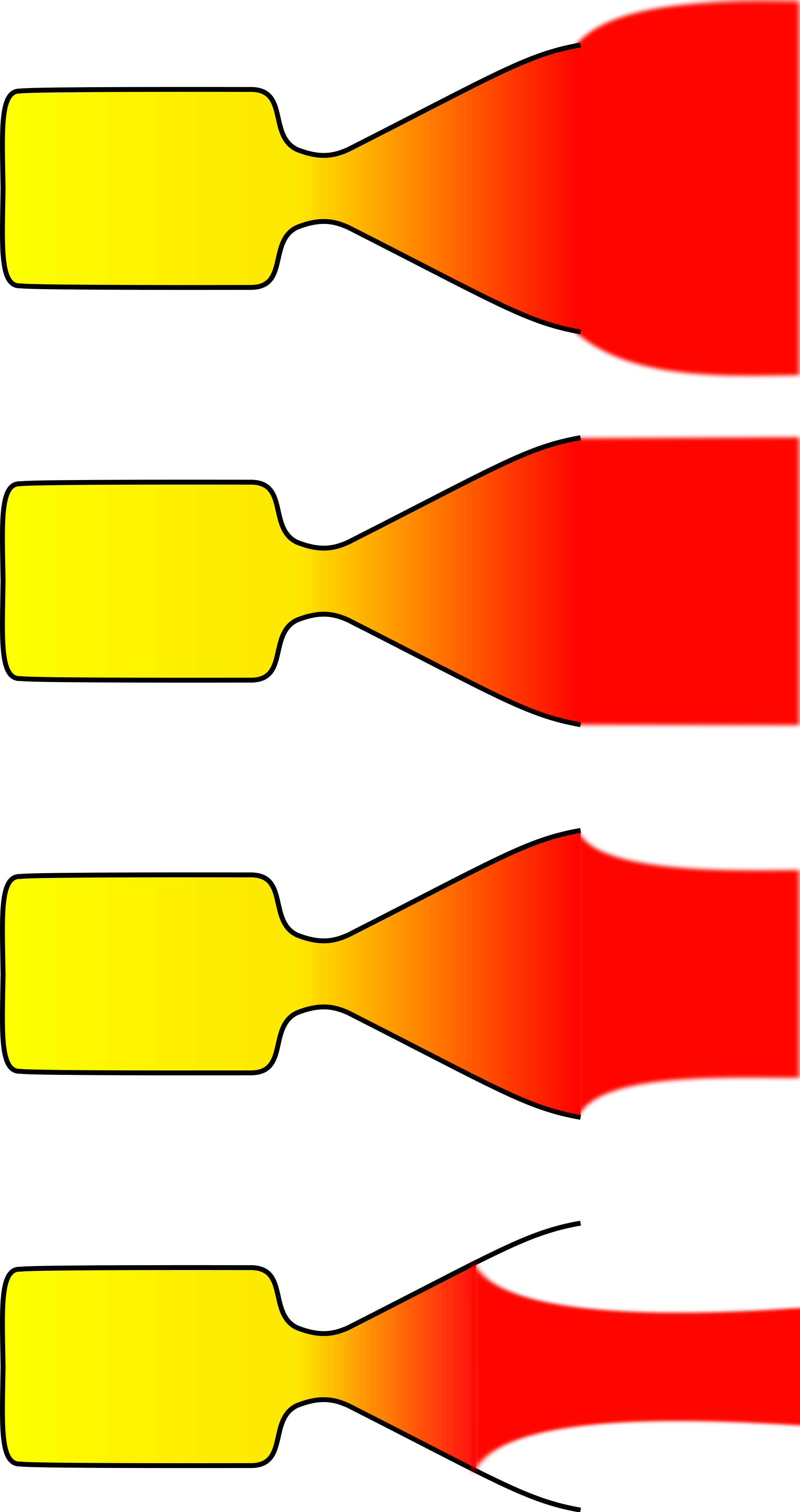
 The term "impulse pressure" or "impulse pressurization" is hardly standard. What I mean to say by it is illuminated by this image showing nozzles not optimized to altitude:


Nozzles can be (top to bottom):
underexpanded,
ambient,
overexpanded,
grossly overexpanded.
If a nozzle is under- or overexpanded, then loss of efficiency occurs relative to an ideal nozzle. Grossly overexpanded nozzles have improved efficiency relative to an overexpanded nozzle (though are still less efficient than a nozzle with the ideal expansion ratio), however the exhaust jet is unstable.[7]


  Rocket engines achieve their best efficiency at vacuum conditions with a large nozzle that allows the exhaust to expand out to near vacuum ambient pressure. However, having a large nozzle at sea level can cause unstable flow that can even tear apart an engine. It's referred to as "flow separation" and is illustrated in the bottom image. 

 Then the idea behind the "impulse pressurization" is to use a large nozzle at sea level but direct a portion of the exhaust flow out towards the sides of the nozzle to counteract this flow separation. That is, use the momentum, the impulse, of the flow to provide outwards pressure against the walls.

 There are two ways this outwards impulse can be provided: you could have the exhaust be swirled by vanes within the nozzle to cause an outwards momentum to the flow or you could have the exhaust be deflected outwards by a shelf within the nozzle that is at an angle to direct the portion of the exhaust near the walls, outwards to impinge against the nozzle walls.
  
 Note that for both of these methods you don't want most of the flow to be swirled or directed outwards but only the portion of the flow near the walls. Note also the swirl vanes or deflecting shelf can be rather far down towards the bottom of the nozzle since the degree of flow separation usually is far down towards the bottom of the nozzle. So for both of these methods most of the thrust attained at vacuum will be maintained at sea level.

 Additionally,  as the rocket increases in altitude the ambient pressure decreases and there is reduced need for this outward pressure. So the portion of the exhaust that is directed outwards will be reduced as the rocket gains altitude, to the point that the full exhaust will be allowed to flow directly downwards when the rocket reaches near vacuum. This can be done in either method by changing the angle of the swirl vanes or deflecting shelf to gradually decrease to null as the rocket achieves altitude.
(Patent pending.) 

An Earlier Patent?
 I have found one patent that attempts altitude compensation by a swirling exhaust flow, but not the deflecting shelf method:

                3,443,384
  SWIRLING FLOW NOZZLE.
James _E. Webb, Administrator of the National Aero
nautlcs and Space Administration with respect to an
invention by Frank X. McKevitt, Palos Verdes Penin
sula, Calif.
Filed May 17, 1967, Ser. No. 640,787
Int. Cl. F02k 1/02, 9/00; B05b 3/00
U.S. Cl. 60--263 4 Claims
ABSTRACT OF THE DISCLOSURE
This disclosure relates generally to rocket engines. It
teaches a method and construction for increasing the effi
ciency of a rocket engine by matching its exhaust gas
pressure with changing ambient pressure. Essentially, a
gas is introduced tangential‘ly into the engine so as to form
a vortex within the nozzle. The size of the vortex can be
used to vary the effective throat area of the nozzle. The
size of the vortex can be changed by varying the relative
amounts of axial and/or tangential flow of gases to the
nozzle.

 There are some differences. This attempts to swirl the combustion gases right within the combustion chamber and thus induce a swirl within the entire exhaust flow inside the nozzle. In contrast, my method will attempt to maintain a large proportion of the vacuum thrust and Isp by only inducing the swirl near the bottom of the nozzle and only for the outer portions of the exhaust flow.

 But a key distinction is that my proposal could be attached to the nozzle of existing engines. That is important to maintaining the idea that altitude compensation is simple and low cost to accomplish.

 Orbital Technologies Corp (ORBITEC) is investigating swirling, vortex motion within the combustion chamber of their engines:

ORBITEC Expands Vortex Rocket Engine Family with Successful Demonstration of New Propellants.
MADISON, Wis. (Nov.  10, 2015) - Sierra Nevada Corporation’s (SNC) wholly-owned subsidiary Orbital Technologies Corporation (ORBITEC) recently completed successful testing and demonstration of three different propellant combinations for its existing 30,000-pound thrust vortex rocket engine. Completing this advancement in less than a year, ORBITEC is rapidly progressing its offering of engines for orbital maneuvering, upper-stage engines that ignite at high altitude, and small-to-medium-scale air and ground launch stage engines.
http://www.sncspace.com/AboutUs/NewsDetails/2243

  Their purpose however is for cooling techniques on the combustion chamber walls not altitude compensation. However, since it uses the same method as the prior patent it may work for altitude compensation as well.


  Bob Clark


UPDATE, January 18, 2016:
  I used the term "impulse pressurization" to describe the pressure provided by a portion of the exhaust flow directed to impinge on the nozzle walls.
 Actually, there is a term in common use for this concept, called "dynamic pressure". For instance during rocket launch, rockets have to be throttled down during the period called "Max Q" where the sum of the ambient pressure at altitude and the force pressure due to the air flow at high speed is at a maximum.

 So I could have called this idea "dynamic pressurization".

Monday, January 11, 2016

Altitude Compensation Improves Payload for All Launchers.

Copyright 2016 Robert Clark

 It is unfortunate that SSTO's have been, incorrectly, deemed unviable. Since altitude compensation has only been thought of in terms of improving the payload of SSTO's, little research has gone into these methods, as SSTO's were not considered worthwhile.

  However, in point of fact altitude compensation improves the payload even for multistage rockets. In the blog post "The Coming SSTO's: Falcon 9 v1.1 first stage as SSTO, Page 2", I showed using the payload estimator by Dr. John Schilling altitude compensation improved the payload of the two-stage Falcon 9 by 25%. 

 Interestingly, the increase for the case of a rocket with side boosters can be as high as 40%. This is the case for the Delta IV Heavy. 

 According to this page the payload to LEO of the Delta IV Heavy is 25,980 kg:

Delta IV Heavy – RS-68A Upgrade.

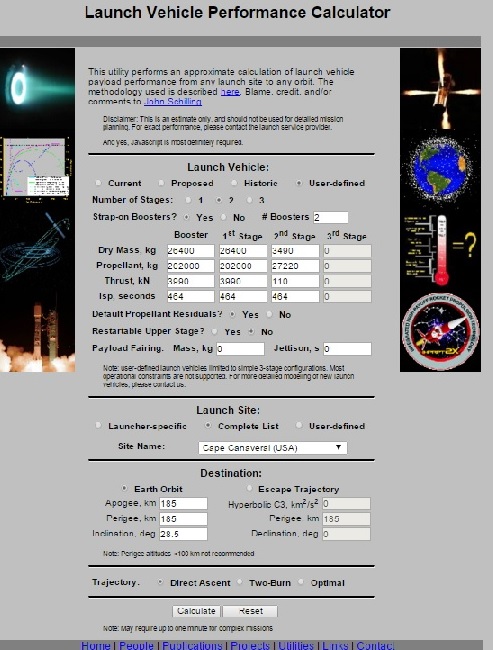
 Using the specifications from this page and inputting the vacuum values for the thrust and Isp, since the Schilling calculator requires inputting the vacuum values as it takes into account the diminution at sea level, the calculator appears as:


 And the results are:

Mission Performance:
Launch Vehicle:  User-Defined Launch Vehicle
Launch Site:  Cape Canaveral / KSC
Destination Orbit:  185 x 185 km, 28 deg
Estimated Payload:  23979 kg
95% Confidence Interval:  19412 - 29682 kg

"Payload" refers to complete payload system weight, including any necessary payload attachment fittings or multiple payload adapters

This is an estimate based on the best publicly-available engineering and performance data, and should not be used for detailed mission planning. Operational constraints may reduce performance or preclude this mission.


 A rather close approximation to the actual payload. 

 Now we'll consider the result when altitude compensating nozzles are used. First, note that there are numerous low cost methods of accomplishing altitude compensation. For instance the RL-10 engine increases its vacuum Isp to ca. 464 s simply by attaching a nozzle extension. Other low cost methods are discussed in "Altitude compensation attachments for standard rocket engines, and applications."

  Increasing the vacuum Isp to 464 s increases the thrust proportionally to (464/414)*3560 = 3,990 N. Then the inputs to the calculator now appear as:


 This gives the result:

Mission Performance:
Launch Vehicle:  User-Defined Launch Vehicle
Launch Site:  Cape Canaveral / KSC
Destination Orbit:  185 x 185 km, 28 deg
Estimated Payload:  33410 kg
95% Confidence Interval:  27137 - 41212 kg

"Payload" refers to complete payload system weight, including any necessary payload attachment fittings or multiple payload adapters

This is an estimate based on the best publicly-available engineering and performance data, and should not be used for detailed mission planning. Operational constraints may reduce performance or preclude this mission.


 About 40% higher than the case without altitude compensation. The reason why it should be expected the increase is higher than in the standard two-stage case is the center core stage in a triple-core launcher spends more of the time at high altitude where the vacuum Isp would obtain.

Altitude Compensation plus Cross-feed Fueling.
 This effect should be even more pronounced with cross-feed fueling. Cross-feed means the center core stage would have its full propellant load after the side boosters are jettisoned so it spends even more time at vacuum conditions.

 The Schilling calculator emulates cross-feed by inputting 2/3rds of the actual propellant load in the field for the side boosters, but increases the value input for the center core propellant to (1 +2/3) times the actual value (See discussion here for an explanation of how the calculator emulates cross-feed.)


 The results are:

Mission Performance:
Launch Vehicle:  User-Defined Launch Vehicle
Launch Site:  Cape Canaveral / KSC
Destination Orbit:  185 x 185 km, 28 deg
Estimated Payload:  48961 kg
95% Confidence Interval:  41112 - 58206 kg

"Payload" refers to complete payload system weight, including any necessary payload attachment fittings or multiple payload adapters

This is an estimate based on the best publicly-available engineering and performance data, and should not be used for detailed mission planning. Operational constraints may reduce performance or preclude this mission.


This is double the initial payload capability without cross-feed and altitude compensation. Note also Cross-feed fueling is not an unknown technology having been used on jet aircraft such as the Concorde for decades and also on the Space Shuttle's OMS engines.

And For the Falcon Heavy? 
 This payload for the upgraded Delta IV Heavy would rival the announced 53 metric tons(mT) LEO payload of the Falcon Heavy with cross-feed fueling and exceed that of the FH without it. But the increase in thrust of the Merlin 1D and increase of propellant load should increase the LEO payload of the Falcon 9 and Falcon Heavy. If the payload to geostationary for the F9 is increased by 30% as announced by SpaceX, then we expect the payload to LEO for the F9 and Falcon Heavy also to be increased a similar amount.  

 Then the current upgraded Falcon Heavy with cross-feed may now be in the 70 mT range. And if altitude compensation also gives this triple-cored launcher a 40% increase in payload that would bring it to the 100 mT range. This is important because this is the range estimated to be required for a manned lunar lander mission by a single launcher, and would be one in a cost range of only $120 million.

  Bob Clark

Tuesday, January 5, 2016

Triple Cored New Shepard as an orbital vehicle.

Copyright 2016 Robert Clark


 Blue Origin made a significant achievement in successfully landing their New Shepard rocket after a suborbital spaceflight:


 As their next development Blue Origin intends to make a several million pound thrust rocket capable of sending 25 metric tons to LEO. This would be a very large and expensive development for their first orbital rocket, comparable in size to the largest orbital rockets available now, larger for example than the Falcon 9.

 I suggest an intermediate development for their first orbital rocket. Running the numbers, their New Shepard suborbital rocket could be used to make an orbital rocket using three cores with a smaller upper stage, a la the Delta IV Heavy.

 It would have a payload to LEO in the range of 3,000 kg, about the size of the Arianespace Vega rocket. The Vega costs in the range of $35 million. Considering the small size of the New Shepard, even at three cores, Blue Origin should be able to beat this price.

 Moreover, this version would have the capability to be reusable. SpaceX is planning to make the three cores of the Falcon Heavy reusable by returning the two side cores to the launch site and recovering the central core by a barge landing out at sea. Quite likely this would work for a 3-cored New Shepard launcher as well.

Specifications of the New Shepard BE-3 engine.


 Here's a formula for calculating the sea level thrust from the vacuum thrust and back pressure:


F = q × Ve + (Pe - Pa) × Ae
where F = Thrust
q = Propellant mass flow rate
Ve = Velocity of exhaust gases
Pe = Pressure at nozzle exit
Pa = Ambient pressure
Ae = Area of nozzle exit
http://www.braeunig.us/space/sup1.htm

 Estimating the nozzle exit diameter as 1 meter, the exit plane area would be: π*0.5^2 = .7854. Then the back pressure to be subtracted off would be 101,000Pa*.7854 = 79,325 N. 
Blue Origin has given the sea level thrust as 110,000 lb, 110,000*4.45 = 489,500 N. So the vacuum thrust is 489,500N + 79,325N = 568,825 N. 

 We also need to calculate the Isp. One other piece of information will allow us to calculate this. This Blue Origin page gives the horsepower of the BE-3 as over 1,000,000 hp:

https://www.blueorigin.com/technology

 The power of a jet or rocket engine is (1/2)*(thrust)*(exhaust velocity). The 1,000,000 hp at sea level is 1,000,000*746 = 746,000,000 watts. Then using the formula the exhaust velocity at sea level is 3,048 m/s, and the Isp is 310 s.

 Since (thrust) = (exhaust velocity)*(propellant flow rate), we also get the propellant flow rate as 489,500/3,048 = 160.6 kg/s. Now we can get the exhaust velocity and Isp at vacuum. From the 568,825 N vacuum thrust, we get the vacuum exhaust velocity as 568,825 N/160.6 = 3,540 m/s, and the vacuum Isp as 360 s.


  It is interesting that the diameter and sea level and vacuum Isp's are close to those of the RL-10A5,  the sea level version of the RL-10 used on the DC-X:

http://www.astronautix.com/engines/rl10a5.htm


Size Specifications for the New Shepard.
 The Blue Origin environmental impact statement:

Final Supplemental Environmental Assessment for the Blue Origin West Texas Launch Site.
February 2014
https://www.faa.gov/about/office_org/headquarters_offices/ast/media/Blue_Origin_Supplemental_EA_and_FONSI.pdf

on p. 4 lists the max dry mass as 30,000 pounds (13,600 kg) and max propellant load as 60,000 pounds (27,300 kg). This corresponds to estimates made of the New Shepard gross mass based on its dimensions.


 We need also a small upper stage. The cryogenic upper stage of the Ariane 4 will suit the purpose, the Ariane H10-3. It had a dry mass of 1,240 kg and a propellant mass of 11,860 kg. The Isp was 445 s with a vacuum thrust of 64.8 kN. However, simply using a nozzle extension as on the RL-10B-2 can give it likewise an Isp of 462 s and vacuum thrust of 110 kN. So we'll use these values.

 Use now Dr. John Schilling's Launch Performance Calculator to estimate the payload. We'll also use cross-feed fueling to increase the payload. Cross-feed fueling is not an unknown technology having been used on jet aircraft such as the Concorde for decades and also on the Space Shuttle's OMS engines.


 To emulate cross-feed fueling with the Schilling calculator for two side boosters, enter in 2/3rds of the actual propellant load into the propellant field for the side boosters. And for the central core enter in (1 + 2/3) times the propellant load in the field for the first stage. (See  discussion here for explanation of how the Schilling calculator emulates cross-feed fueling.)


 So in the dry mass fields for the side boosters and first stage enter 13,600 kg. And in the propellant field for the side boosters enter 18,200 kg and 45,500 kg for the first stage. For the second stage enter 11,860 kg for the propellant and 1,240 kg for the dry mass.


 In the thrust fields and Isp fields enter in the vacuum values. So for the side boosters and first stage enter 568.8 for the thrust in kilonewtons and 110 for the second stage. In the Isp fields enter 360 for the side boosters and first stage Isp in seconds and 462 for the second stage. 


 For the "Restartable upper stage" option check "No", otherwise the payload will be reduced. Select Cape Canaveral as the launch site and enter 28.5 for the launch inclination in degrees to match the latitude of the launch site.


 The calculator gives:


Mission Performance:
Launch Vehicle:  User-Defined Launch Vehicle
Launch Site:  Cape Canaveral / KSC
Destination Orbit:  185 x 185 km, 28 deg
Estimated Payload:  3420 kg
95% Confidence Interval:  2766 - 4205 kg

"Payload" refers to complete payload system weight, including any necessary payload attachment fittings or multiple payload adapters

This is an estimate based on the best publicly-available engineering and performance data, and should not be used for detailed mission planning. Operational constraints may reduce performance or preclude this mission.


  This would be using an Arianespace upper stage. But this would be a competitor to their Vega launcher so that is problematical. Blue Origin could use instead the Rl-10B2 engine and their own constructed upper stage. The RL-10 though is a rather expensive engine. Another possibility is the 25,000 lb thrust hydrolox engine being developed by XCOR.


Altitude Compensation Increases Payload Even for Multistage Vehicles.

 It is unfortunate that SSTO's have (incorrectly) been deemed unviable. Since altitude compensation has only been thought of in terms of improving the payload of SSTO's, little research has gone into such methods, with SSTO's not being considered worthwhile.

 However, in point of fact altitude compensation improves the payload even for multistage rockets. As with the RL-10B-2 we can get a vacuum Isp of 462 s on the New Shepard hydrolox engine simply by the addition of a nozzle extension. Other methods of accomplishing it are discussed in the blog post "Altitude compensation attachments for standard rocket engines, and applications."


 Increasing the Isp will also increase the thrust proportionally. So at a 462 s Isp for the BE-3, the thrust becomes 568.8*(462/360) = 730 kN. Entering these values into the thrust and Isp fields for the side boosters and first stage gives the result:


Mission Performance:
Launch Vehicle:  User-Defined Launch Vehicle
Launch Site:  Cape Canaveral / KSC
Destination Orbit:  185 x 185 km, 28 deg
Estimated Payload:  5302 kg
95% Confidence Interval:  4359 - 6438 kg

"Payload" refers to complete payload system weight, including any necessary payload attachment fittings or multiple payload adapters

This is an estimate based on the best publicly-available engineering and performance data, and should not be used for detailed mission planning. Operational constraints may reduce performance or preclude this mission.


 This now is a serious payload capability. Note for example NASA awarded Orbital Sciences with a billion dollar contract to deliver payload to the ISS with their Antares rocket with a 5,000 kg payload to LEO capacity.


 Bob Clark


UPDATE, February, 3, 2016:

 Jonathan Goff on his SelenianBoondocks.com blog raised the possibility that a single New Shepard could serve as a booster for an orbital rocket. I confirmed it could at the 1 to 2 metric ton payload range by using the same type of hydrolox upper stage as discussed above in the triple-cored case:

New Shepard as a booster for an orbital launcher.
http://exoscientist.blogspot.com/2016/01/new-shepard-as-booster-for-orbital.html

 It could also serve as a booster for a smaller launcher by using instead one of the Star solid rocket upper stages, giving a few hundred kilos payload. This would have the advantage that little extra development would be required.

 Plus, it may allow Blue Origin to beat SpaceX at reusing a booster for an orbital launcher.

Saturday, December 12, 2015

Hovering capability for the reusable Falcon 9, page 3: hovering ability can increase the payload of a RLV.

Copyright 2015 Robert Clark

 Blue Origin successfully landed their New Shepard rocket after reaching suborbital space:


 Observing the last portion of the video showing the landing, deviations from the vertical are visible but the ability to hover allowed it sufficient time to correct.

 Comparing this to the SpaceX Falcon 9 failed attempts at landing it is apparent the inability to hover for the F9 did not allow it sufficient time to make the needed corrections.

 SpaceX has said they want their next test landing to be on land at the launch site. My opinion, they might succeed on the next test or two but they will always have failures without hovering ability.

Merlins in a pressure-fed mode.
 Achieving hovering is not even difficult. In the blog post "Hovering capability for the reusable Falcon 9, page 2: Merlin engines in a pressure-fed mode?" I suggested giving the Merlin the ability to run in a pressure-fed mode. The question was whether this was technically feasible. I found in fact that this process of giving a turbopump powered engine a pressure-fed mode, called an idle mode, had been successfully tested during the Apollo days on the J-2 upper stage engine.

 In giving the J-2 an idle mode though, it was changed from the gas generator cycle that is used by the Merlin 1D to a tap-off cycle:

Rocketdyne J-2.
https://en.wikipedia.org/wiki/Rocketdyne_J-2#J-2S

 However, there is an engine that uses the gas generator cycle and has an idle mode, the LE-5 upper stage engine of the Japanese space agency:

Development of the LE-X engine.
https://www.mhi-global.com/company/technology/review/abstracte-48-4-36.html

 In this idle mode though the thrust is significantly less than at full thrust, only 3% in the LE-5 case. If it is a similar low percentage for the Merlin's then all 9 engines would have to be used in this idle mode to allow it to hover on landing.

 The idle mode has an additional advantage since it does not use the turbopumps. It could be used to burn both residual liquid propellant and gases in the tanks. This would mean much less residual fluid would be left in the tank. This then reduces the amount of propellant that needs to be kept on reserve for the landing.

 Elon Musk has also recently said in his Twitter account that the F9 first stage has single-stage-to-orbit (SSTO) capability. For an SSTO the residuals in a first stage can subtract a significant amount from the payload it can deliver to orbit. Then the ability to run in an idle mode with minimal residuals left over can significantly increase the payload for an SSTO. So this would be a further advantage of giving the Merlins an idle mode.

Hovering by use of flexible nozzle extensions.
 In the blog post "Altitude compensation attachments for standard rocket engines, and applications", I discussed another method of achieving hovering capability, attaching nozzle extensions to the bottom of the engines that would allow restriction of the thrust. The flexible high temperature materials already exist in the reentry materials used in NASA's Inflatable Re-entry Vehicle Experiment (IRVE). This has the advantage that the nozzle extension would have to only be applied to the one central engine to reduce its thrust on landing.

 However, the extendable nozzle attachments also have an advantage to the SSTO case. By using an extension that can be retracted at launch and fully extended at high altitude, you can get engines usable at sea level that can reach the high vacuum Isp's usually reserved for upper stage engines. In this way the 311 s vacuum Isp of the Merlin 1D can be raised to the same level of 340 s as the Merlin Vacuum. An increase in the vacuum Isp to this extent can as much as double the payload of a SSTO.

 Note that both of these techniques, idle mode or flexible nozzle extensions, would mean hovering capability can actually increase the payload rather than reduce it.

    Bob Clark

Tuesday, October 27, 2015

Nuclear powered VASIMR and plasma propulsion doable now, Page 3: High efficiency conversion enables zero radiator mass.

Copyright 2015 Robert Clark

Low Radiator Mass at High Efficiency.
 Discussions on various forums have argued the point that actually low conversion efficiency is preferred to save on radiator mass. The idea behind this is that by the Stefan-Boltzmann Law, energy is radiated away according to the fourth power of the temperature. So high thermal energy conversion efficiency resulting in low output temperatures would require larger radiators than with low conversion efficiency with high output temperature. This is explained on this page:

Heat Radiators.
"As an example of the severity of this problem, let us examine the case of a
simple nuclear power plant whose energy conversion efficiency from thermal
to electric is approximately 10 percent. The plant is to generate 100 kW of
useful electricity. The reactor operates at approximately 800 K, and a
radiator with emissivity equal to 0.85 would weigh about 10 kg/m2. The
thermal power to be dissipated from the reactor would be about 1 MW. From
the Stefan Boltzmann Law, the area of the radiator would be about 50 m2 and
the mass approximately 500 kg. This seems quite reasonable.
However, we must assume that the electricity generated by the power plant,
which goes into life support systems and small-scale manufacturing, would
eventually have to be dissipated also, but at a much lower temperature
(around 300 K). Assuming an even better, aluminum radiator of about 5 kg/m2,
with again an emissivity of 0.85, in this case we find that the area of the
low temperature heat rejection component is 256 m2, with a mass approaching
1300 kg."

http://www.projectrho.com/public_html/rocket/basicdesign.php#radiators

 This web site by the way provides a nice collection of the work that has been done on advanced space propulsion systems.

 An additional problem though in regards to low efficiency conversion is that you need higher mass for the reactor and larger amounts of radioactive material that needs to be launched to orbit. For example in the blog post:

"Nuclear powered VASIMR and plasma propulsion doable now, Page 2,"
http://exoscientist.blogspot.com/2015/10/nuclear-powered-vasimr-and-plasma.html ,

I suggested running the reactor at low power to extend the lifetime. In this mode the reactor weighing 2,200 kg would put out 8 megawatts using 200 kg of uranium fuel. If instead of the high conversion efficiency I was aiming for, we selected 10% conversion efficiency, we would need a 10 times larger reactor and 10 times more radioactive fuel. This would put the mass of the reactor at 22,000 kg and the uranium fuel at 2 tons.

 There might be some methods to reduce the heat that needed to be radiated away in the high efficiency scenario. For example Stirling engines can operate even at low temperatures. We could use these to make use of the heat at low temperatures coming from the turbines of  our generator.

 There is also research on lightweighting radiators such as by using carbon-carbon composites:

High Conductivity Carbon-Carbon Heat Pipes for Light Weight Space Power System Radiators.
NASA/TM—2008-215420
http://ntrs.nasa.gov/archive/nasa/casi.ntrs.nasa.gov/20080045532.pdf

 However an interesting possibility exists that we might not need any radiators at all for the high efficiency case. 

  In the high efficiency case at low output temperature, you can bring the output of the working-fluid down to cryogenic temperatures, as for example for a de Laval nozzle exhausting out to vacuum. If the electric generator equipment is at room temperature, or chilled to decrease resistance and therefore increase power output and specific electric power, then we can have the working-fluid output temperature be lower then the electric generator equipment. So it can used to remove the heat given to the electric generator due to small proportion of thermal not converted to electric power.

 Note this would not obtain for the low efficiency, high output temperature case. If the output is at, say, 800 K to 1,000 K, then by the Second Law of Thermodynamics (Clausius form) we could not use this to cool the generator operating at, say, 300 K or below.

 However, by exhausting down to cryogenic temperatures we could use the cold working-fluid to cool the generator. 

 We need also to cool the turbine. Turbines can be at 90%+ efficiency. The turbine however will be receiving the working fluid at the output temperature. We can though allow the working-fluid to expand further after exiting the turbine to drop to a lower temperature. This then could be used also to cool the turbine.

 An additional factor to provide cooling are the nozzle extensions used for high expansion ratio upper stage engines. For example the RL10-B2 nozzle extensions increase the area ratio to 285-to-1.


 The nozzle extension doubles the weight of the RL10 engine from 150 kg to 300 kg, so weighs 150 kg. The upper part of the nozzle is regeneratively cooled but the carbon-carbon extension is only radiatively cooled. The RL10-B2 engine puts out ca. 250 MW of power measured by its 110 kN thrust and 465.5 s Isp. 

 Because of the low mass of the spacecraft due to the short travel time the power level for the plasma propulsion can be less than 10 MW. Then, with regeneratively cooled upper nozzle section, the nozzle extension to bring the exhaust output down to cryogenic temperatures for this power level might only be 1/25th as large, so only 6 kg(!)

Correction to fuel replacement mass.
 In the comments section to the "Nuclear powered VASIMR and plasma propulsion doable now, Page 2" post, Rok Adamlje noted that my estimate for the fuel canister mass that needed to be replenished was too small. I was taking it to be just the uranium fuel mass when the actual total canister mass may be ten times higher.

 In the section there titled, "Long Life by Multiple Nuclear Fuel Canisters", I calculated the average specific power when using 468 fuel canisters at 200 kg each to last the 39 days of the flight. If we take the fuel canisters instead to be 2,000 kg then we can still get high average specific power by jettisoning the used canisters: 

 The rest of the engine mass, which will be fixed, is a small proportion of the total mass of the fuel canisters so we'll calculate the average specific power based on just the total fuel canister mass. The average specific power will be:

  545 MW       545 MW                  545 MW         545 MW
 ------------ +  --------------- + ... +  -------------  +  -------------
  468*2,000      467*2,000                2*2,000          1*2,000
-------------------------------------------------------------------------
  468


545MW     1               1                    1            1
 --------- (-------- +    ------- + ... +  --------  +  -------)
  2,000       468          467                  2            1
=  ----------------------------------------------------------------------
         468


 The summation in the numerator is the sum of the reciprocals of the natural numbers and is well approximated by the natural log function ln(n). So this will be:

(545,000,000/2,000) *(ln(468)/468) = 3,580 W/kg, still above the 1,000 W/kg level needed for the plasma propulsion.

 Note though the length of time the engine will need to be run is actually less than 39 days because of the small mission size due to the fast travel time. So we'll need fewer replacement fuel canisters and the actual average specific power will be greater.

 Also it could be much of the canister(s) can be reused, primarily replacing just the uranium fuel. This will also increase the average specific power.

      
        Bob Clark

Could Blue Origin develop a lander for Artemis III?

Copyright 2025 Robert Clark SpaceX is coming under increasing criticism for its delay in developing the Starship lunar lander: U.S. Is Losin...