Thursday, August 13, 2015

Orbital rockets are now easy.

Copyright 2015 Robert Clark

Falcon 1 Upper Stage Based Orbital Launcher.
 In the blog post "On the lasting importance of the SpaceX accomplishment" I suggested that SpaceX's low cost, commercial approach to developing the Falcon 9 will lead to this being emulated by other launch providers and then, eventually, to spaceflight becoming routine. However, ironically, it might turn out their simplest development and one they dispensed with will have the fastest effect towards making orbital access routine.

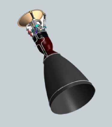
  It's the Falcon 1 upper stage. Compared to the first stage and certainly compared to the Falcon 9, it's a rather simple stage only using a pressure-fed engine, the Kestrel. 


Kestrel engine

  Pressure-fed engines and stages are much easier to develop than pump-fed ones. For instance there are the rockets developed by Armadillo Aerospace, Masten Space Systems, and Garvey Spacecraft Corporation. 

 And this was also the case for the Project Morpheus lunar lander stage. In the blog post "The Morpheus lunar lander as a manned lander for the Moon", I discussed the NASA's Project Morpheus emulating a low-cost commercial space approach was able to develop two Morpheus landers for only $14 million. And actually the parts only costs were in the range of $750,000 per lander.

 The construction costs for pressure-fed engines can also be low cost. For instance Project Morpheus was able to produce their engines at a cost of only $60,000:

NASA dreams of future Morpheus project templates.
March 14, 2015 by Chris Bergin
The main engine – which was also tested at the Stennis Space Center – could throttle at a ratio of 4 to 1, ranging between 1,400 and 5,400 pounds thrust. All Morpheus engines were custom designed and built specifically for Morpheus and only cost $60,000 each.

 The specifications for the Falcon 1 upper stage are given here:

Falcon 1.

 It has a 360 kg dry mass and 3,385 kg propellant mass, and a 3,175 kilogram-force vacuum thrust and 327 s vacuum Isp using the Kestrel engine. This is an upper stage engine however with a long nozzle that can't be used at sea level. In the post "Altitude compensation attachments for standard rocket engines, and applications" I described various attachments to be made to existing engines to give them altitude compensation ability. 

 However, since pressure-fed engines are so comparatively low-cost they could be designed from the beginning to have aerospike nozzles. There is for instance the aerospike engine of Garvey Spacecraft. And Firefly Space Systems  will construct an aerospike nozzle by using numerous small engines arranged around a central spike.

 The question though is how much thrust could be developed with the Kestrels at sea level using altitude compensation. I'll estimate from the formula for Isp for a rocket engine:

The ideal exhaust velocity is given by

where k is the specific heat ratio, R* is the universal gas constant (8,314.4621 J/kmol-K in SI units, or 49,720 ft-lb/(slug-mol)-oR in U.S. units), Tc is the combustion temperature, Mis the average molecular weight of the exhaust gases, Pc is the combustion chamber pressure, and Pe is the pressure at the nozzle exit.
http://www.braeunig.us/space/propuls.htm#Isp


 The pressure factor at the end reduces the Isp at sea level. The specific heat ratio k is about 1.24 for kerolox. The Kestrel operates at a chamber pressure of 135 psi. Then the pressure factor is:
sqrt(1-(14.7/135)^(.24/1.24)) =  .591. So the Isp at sea level is 327*.591 = 193 s and the sea level thrust is .591*3,175 = 1,876 kilogram-force. 

 Note for this estimate to be valid you have to have altitude compensation so that the engine has optimal performance at sea level, i.e., you don't have the back-pressure loss that results from non-optimal expansion.

 Because of the 3,745 kg gross mass of the stage though, we need to reduce the propellant load to be loftable by the single Kestrel at the 1,876 kilogram-force sea level thrust. We'll reduce the propellant load by a factor of .45, so to .45*3,385 = 1,520 kg. We want also to maintain the relatively high mass ratio for the stage so we'll reduce the tank size. The tank mass is proportional to the propellant mass. Subtracting off the 52 kg mass of the Kestrel leaves us 308 kg in the stage dry mass. Multiplying this by .45 gives .45*308 = 138.6 kg. Adding on the 52 kg mass of the Kestrel gives a dry mass of 190 kg. 

 Other elements of a rocket stage such as the insulation, wiring, avionics do not scale linearly with propellant mass as does tank mass. However, since for pressure-fed stages the dry mass is so dominated by the tank mass this gives an approximate value of the stage mass when you scale down the stage size. 

 Moreover we can further reduce the dry mass by using composite propellant tanks. Microcosm, Inc. is making small-sized composite tanks that could be used for the purpose. NASA research has shown composite tanks can save 30% off the mass of aluminum-lithium tanks. Since Al-Li tanks save about 25% off the weight of standard aluminum tanks, this means composites can save about 50% off the weight of standard aluminum propellant tanks. 

 To estimate the mass this could save for this application, historically the propellant mass to tank mass ratio for kerolox for standard aluminum tanks is about 100 to 1. Note though this is for pump-fed engines that only need their stages at about 2 bar, about 30 psi. When the tank pressure is increased for pressure-fed engines the tank mass is correspondingly increased. The Falcon 1 upper stage tanks are kept at 200 psi pressure. So for our propellant mass of 1,520 kg, the tank mass assuming standard aluminum might be (1,520 kg/100)*(200 psi/30 psi) = 101 kg. Then a  reduction of 50% in the tank mass would cut 50 kg from the dry mass to bring it to 140 kg. However, we'll calculate here the payload using 190 kg dry mass number, as the dry mass here is approximate since some components of the stage won't actually scale proportionally with the stage size.

Cross-Feed Fueling for Multiple Cores.
 To increase payload we'll use cross-feed fueling. Note that cross-feed fueling is actually a well-understood technology, having been used on the Space Shuttle OMS engines:

Propellant Storage and Distribution.
"The propellant storage and distribution system consists of one fuel tank and one oxidizer tank in each pod. It also contains propellant feed lines, interconnect lines, isolation valves and crossfeed valves.
"The OMS propellant tanks of both pods enable the orbiter to reach a 1,000-foot- per-second velocity change with a 65,000-pound payload in the payload bay. An OMS pod crossfeed line allows the propellants in the pods to be used to operate either OMS engine."

 And it has also been used for decades for jet airliners:

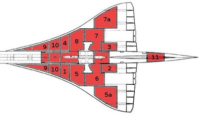
Concorde.
Balancing by Fuel-Pumping.
The Concorde Tank-Schematic:

"1 + 2 + 3 + 4 are the Collector-Tanks, feeding the engines directly. Usually they feed there counterpart engines – but they can be cross-switched to feed more and/or other engines at the same time.
5 + 7 and 8 + 6 are the Main-Transfer Tanks, feeding the 4 Collector-Tanks. Initially 5 + 7 are active. If those are empty 6 + 8 take over (or must be activated from the Engineering Panel!).
5a + 7a are Auxiliary-Tanks (to 5 and 7).
9 + 10 are the Trim-Tanks for balancing forward
11 is the Trim-Tank for balancing afterward"

 To emulate rocket cross-feed fueling with the Schilling Launch Performance Calculator, note that during the parallel burn portion of the flight the propellant for the center core engines is coming from the side booster stage(s). This ensures that the center core will have a full propellant load during its solo burn portion of the flight, after the side booster(s) are jettisoned. 

 So the total amount of propellant burned during the parallel burn portion is that of the side booster(s) only. But the Schilling Calculator assumes the amount of propellant burned in the center core during the parallel burn is the same as the amount burned in each side booster. So enter in the Calculator for the booster propellant load a fraction of the actual propellant load of a core equal to the number of side boosters divided by the number of cores. So if you're using 2 cores with one used as a side booster enter in the Calculator booster column 1/2 the amount of the actual core propellant load. And if using 3 cores with 2 used as side boosters, enter in 2/3rds the actual core propellant load in the booster section. This will ensure the Calculator interprets the total propellant burned during the parallel burn portion is that of the actual side booster(s) only.

 But you also want the Calculator to take the amount of propellant burned during the center core's solo burn portion of the flight as that of a full propellant load. Since it is already taking it to have burned the same amount as what the side boosters have burned during the parallel burn portion, add this amount onto the actual propellant load of a core and enter this into a first stage column of the Calculator. For the other specifications for both booster(s) and center core such as Isp, dry mass, and thrust enter in the actual values.

 We'll calculate here the case for using two side booster of same size as the central core. Enter in the Schilling calculator the dry mass of 190 kg for the boosters and the first stage, which is the central core. For the thrust and Isp for the boosters and the first stage, enter in the vacuum Isp of 327 s and vacuum thrust of 31.1 kN in the calculator. However, to emulate cross-field fueling, for the propellant fields enter in (2/3)*1,520 kg = 1,013 kg in the booster section and 1,013 kg + 1,520 kg = 2,533 kg in the first stage section. Choose Cape Canaveral as the launch site and 28.5 degrees as the launch inclination to match the latitude for the launch site. For the "Restartable Upper Stage" select "No", otherwise the payload will be reduced. Then the calculator gives the result:

Mission Performance:
Launch Vehicle:  User-Defined Launch Vehicle
Launch Site:  Cape Canaveral / KSC
Destination Orbit:  185 x 185 km, 28 deg
Estimated Payload:  63 kg
95% Confidence Interval:  19 - 116 kg

"Payload" refers to complete payload system weight, including any necessary payload attachment fittings or multiple payload adapters
This is an estimate based on the best publicly-available engineering and performance data, and should not be used for detailed mission planning. Operational constraints may reduce performance or preclude this mission.


 We could get over 100 kg if we used three side cores. 

Methane for Improved Performance.
 We could also increase the payload using methane instead of kerosene as the fuel. For booster stages, methane has about the same performance as kerosene since the greater density for kerosene makes up for its lower Isp. But for upper stages methane offers better performance since it would give a lighter stage that had to be lofted by the lower stages. So if you wanted to use identical stages for simplicity and cost, methane would be the preferred fuel.

 There is also a key practical reason why methane might be preferred. NASA has developed the methane-fueled engine for the Morpheus rocket stage. With NASA's Technology Transfer program the technical info on the engine would also be shared at least for American companies. Then you would only have to pay the ca. $60,000 construction costs for the engine. 

 Considering that both the Kestrel and Morpheus engines are reusable this already low cost launcher can cut the cost to space considerably. It then could be used for DARPA's proposed reusable launchers discussed here: "NASA Technology Transfer for suborbital and air-launched orbital launchers." In an upcoming blog post I'll also show that using a single one of these cores, it can be used as either the reusable first stage booster, or the air-launched orbital stage for these DARPA programs.

Scale-up to Large Launchers. 
 Note this is a 5,130 gross mass launcher to launch a 63 kg payload. Pressure-fed stages scale up more easily than pump-fed ones since you don't have the complexity of creating a turbopump for the larger size engines. The Mercury spacecraft that carried John Glenn massed 1,300 kg. Using modern materials we could probably make a one-man capsule for 500 kg. Then we would only have to scale up our 3 core launcher by a factor of 8 to launch a one-man capsule to orbit. This would be a 41,000 kg gross mass launcher compared to the 120,000 kg gross mass Atlas rocket that launched John Glenn to space.

  Bob Clark


Tuesday, August 11, 2015

Propellant depots for interplanetary flight.

Copyright 2015 Robert Clark


 In the blog post "The Coming SSTO's: Applications to interplanetary flight" I calculated that IF we have propellant depots at both departure and arrival points then a single Falcon 9 first stage could do ALL the propulsive steps for a flight to Mars, from the LEO departure, to insertion into low Mars orbit, to Mars landing, to Mars liftoff, to departure back towards Earth. 

 The argument there was that this was another key advantage of SSTO's that they would have this capability. But it is important to note that this would be true for all the currently existing medium lift first stages at ca. 20 metric ton (mT) dry mass (without their needing to be SSTO), from the Atlas V, to the Delta IV, to the Soyuz, to the Ariane 5 core, to the Long March 2F, to the H-II. Then all the current spacefaring nations would have the ability to do manned Mars missions with currently existing rockets IF propellant depots are already in place. This is compared to the ca. 1,000 metric ton (mT) total mass estimates for the NASA Mars Design Reference Architectures. 

 Interestingly, when you consider the delta-v requirements for flights to the Moon, Venus, Mercury, and near Earth asteroids then this would also be true for these destinations with propellant depots already in place, perhaps at their Lagrange points. See for instance the Excel spreadsheet describing the Hohmann transfer flights linked on Hop David's page Cosmic Train Schedule. Then propellant depots make possible the long desired goal of Solar System colonization, at least within the inner solar system.

 The Mars flight described in "The Coming SSTO's: Applications to interplanetary flight" using single F9 stage would be flying the usual Hohmann transfer orbit of several months duration. The problems of such space trips in BEO space for several months have been much discussed, from bone and muscle loss, to radiation damage, to the recently discovered eye damage. In fact William Gerstenmaier, head of NASA's human spaceflight division, has said the NASA Mars mission architectures that might take 900 days total round trip are  unworkable:

Yes, NASA really is reconsidering the moon, and here’s why that’s important.
Posted on April 6, 2015 | BY ERIC BERGER
http://blog.mysanantonio.com/newswatch/2015/04/yes-nasa-really-is-reconsidering-the-moon-and-heres-why-thats-important/

 Gerstenmaier suggested, as have many others outside of NASA, that using lunar derived fuel in orbital propellant depots would make Mars missions easier and cheaper. But what has not been discussed is that with propellant depots in orbit the flight times can be cut down from the months long duration to only weeks long. That is, flight times that were thought would need advanced propulsion such as VASIMR plasma or nuclear propulsion could be done by chemical propulsion alone, and in fact using currently existing chemical propulsion stages.

Lightweight Habitat Modules.
 A key fact that needs to be kept in mind is that when the flight times are much shorter then you can use smaller, lighter habitats that need to be transported. This results in a smaller flight vehicle. We can show once again using a single medium-lift first stage we can send a ca. 6 mT habitat to Mars in about 35 days.

 In the post "Budget Moon flights: lightweight crew capsule", I discussed the Phoenix lightweight crew capsule of the University of Maryland aerospace department:

Phoenix: A Low-Cost Commercial Approach to the Crew Exploration Vehicle.

http://rascal.nianet.org/wp-content/uploads/2015/07/2006-RASC-AL-UMD-Tech-Paper.pdf

 This has a pressurized volume of 30 cubic meters with food, air, and water for a crew of 3 for 12 days at a ca. 2 metric ton (mT) dry mass. So putting three together will give enough consumables for the 3 crew for 36 days at a 90 m3 volume and 6 mT mass.

Calculation of flight time to Mars using the Oberth Effect.
 Another advantage of having propellant depots in cis-lunar space such as at L2 and departing from there is the Oberth effect. This is the increase in the rockets delta-v you can get by falling deep into the departure planets gravity well and firing the engines at closest approach. I like this explanation of the effect in Robert Heinlein's book The Rolling Stones:
A gravity-well maneuver involves what appears to be a contradiction in the law of conservation of energy. A ship leaving the Moon or a space station for some distant planet can go faster on less fuel by dropping first toward Earth, then performing her principal acceleration while as close to Earth as possible. To be sure, a ship gains kinetic energy (speed) in falling towards Earth, but one would expect that she would lose exactly the same amount of kinetic energy as she coasted away from Earth.
The trick lies in the fact that the reactive mass or 'fuel' is itself mass and as such has potential energy of position when the ship leaves the Moon. The reactive mass used in accelerating near Earth (that is to say, at the bottom of the gravity well) has lost its energy of position by falling down the gravity well. That energy has to go somewhere, and so it does - into the ship, as kinetic energy. The ship ends up going faster for the same force and duration of thrust than she possibly could by departing directly from the Moon or from a space station. The mathematics of this is somewhat baffling - but it works.
http://www.projectrho.com/public_html/rocket/mission.php#id--Oberth_Effect

  On that www.projectrho.com page is given this formula for calculating the Oberth effect:
To actually calculate the bonus delta V you will get from the Oberth Maneuver:
Vf = sqrt((Δv + sqrt(Vh2 + Vesc2))2 - Vesc2)
Δv = sqrt(Vf2 + Vesc2) - sqrt(Vh2 + Vesc2)
where:
Vf = final velocity (m/s)
Vh = initial velocity before Oberth Maneuver(m/s)
Δv = amount of delta V burn at periapsis (m/s)
Vesc = escape velocity at periapsis (m/s)
 For the propulsion stage we'll use the Ariane 5 "G" core. This has 158 mT propellant load and 12 mT dry mass at 434 s Isp engine. We'll make some small modifications to increase performance. The Ariane 5 core launches from ground so has a intermediate size nozzle to operate at sea level and vacuum. For our use, we're only using it for vacuum so we'll give it a nozzle extension such as on the RL-10B2 Centaur engine to increase the Isp to 462 s. We'll also remove a forward skirt on the core called the "JAVE", from the French "Jupe AVant Equipée", that is used to attach the solids to the Ariane 5. This massed 1,700 kg, bringing the dry mass now down to 10,300 kg.

 Then this can produce an Isp with a 6 mT payload of:

462*9.81ln(1 + 158/(10.3 + 6)) = 10,700 m/s = 10.7 km/s.

  Now use the Oberth effect to calculate the speed after the periapsis burn:

Vf = sqrt((10.7 + 11.1)2 - 11.12) = 18.8 km/s.

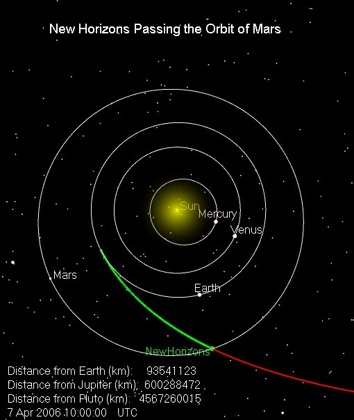
 For departure speeds  this high the trajectory is nearly straight-line despite the influence of the Sun. The New Horizons mission gives an example of fast travel times possible with chemical propulsion:

Pluto-Bound Probe Passes Mars’ Orbit.
by Tariq Malik, Staff Writer | April 07, 2006 01:45pm ET
"It's pretty amazing," New Horizons principal investigator Alan Stern told SPACE.com. "It's a straight line across the Solar System. There are hardly any curves because this is so fast." 
New Horizons sped past Mars' orbit some 151 million miles (243 million kilometers) from the Sun at a rate of about 13 miles (21 kilometers) per second. The red planet, however, trailed behind the spacecraft at a distance of about 186 million miles (299 million kilometers), mission managers said, adding that New Horizons was closer to Earth than Mars.
http://www.space.com/2263-pluto-bound-probe-passes-mars-orbit.html

Passing the Orbit of Mars.
New Horizons' trailblazing journey to the solar system's outermost frontier took it past the orbit of Mars at 6 a.m. EDT (1000 UTC) on April 7, 2006 - 78 days after the spacecraft launched.
http://pluto.jhuapl.edu/Mission/Where-is-New-Horizons/Passing-Planets/Passing-Planets-Mars.php

 The distance between Mars and Earth at the time was about 90 million km. The 2018 Mars opposition on the other hand is a particularly close approach at about 58 million km away. At that time for New Horizons to make the trip would have been about 48 days.

 Our flight would be at a faster speed of 18.8 km/s compared to the 12 km/s of New Horizons. Then for the close 2018 opposition, the approximate flight time would be 58,000,000/(18.8*3,600*24) = 35.7 days. This from using a single Ariane 5 core stage, launched dry, fueled at an L2 propellant depot.

Fuel for the propellant depots.
 Because of its proximity the Moon has been often offered for the fuel source for the orbital propellant depots. This would be simpler if the process needs to be supervised by humans. However, some near Earth asteroids have a much smaller delta-v and very much smaller gravity for delivering the fuel to the cislunar system:

Asteroid Retrieval Feasibility Study.
2 April 2012
http://kiss.caltech.edu/study/asteroid/asteroid_final_report.pdf

 Much of the discussion of retrieving asteroids has been about the solar electric ion propulsion used and that perhaps it would cost $2.6 billion to develop. But I was surprised in the report that it also discussed doing it with LH2/LOX chemical propulsion and how little propellant it would use. First it notes that an asteroid such as 2008HU4 at closest approach would require only a 170 m/s (!) delta-v to bring it to lunar orbit. Then in figure 19 on p. 43 is given a comparison between the propellant required for LH2/LO2, N204/MMH, and SEP propulsion for this asteroid at an assumed 1,000 mT mass.

 Surprisingly, for the LH2/LO2 case it is less then 40 mT for a 1,000 mT payload! This is because of course it is only a 170 m/s delta-v. But this means for the 500 mT case that was initially cited for the mission it would be less than 20 mT propellant load, and a LH2/LOX propulsion stage this size is already available in the Centaur. Note also that at an only 170 m/s delta-v to get the Centaur to this asteroid, you would only need to use about 1 mT out of the 20 mT propellant load.

 Since the chemical propulsion would have greater thrust, the mission return time would also be significantly less than the 10 years for the SEP propulsion.

 Planetary Resources, Inc. is launching small telescopes to prospect for asteroids either for mineral resources or for water for propellant. Many asteroids or extinct comets will have large amounts of water ice. Rather than using many rovers to scoop up the surface material for processing, there is an easier approach. Parabolic trough mirrors could be positioned around the four sides of a rectangle on the surface and angled inwards to cut out an upside down triangular prism shaped portion of the asteroid.


Parabolic trough mirror.


Triangular prism.

 Because of the low gravity of the asteroid the water and dust vaporizing will tend to lift the block off the surface.

 Another possibility would be to use microwaves to evaporate the water ice:

Microwaving Water from Moondust.
October 7, 2009.
"We believe we can use microwave heating to cause the water ice in a lunar permafrost layer to sublimate – that is, turn into water vapor. The water vapor can be collected and then condensed into liquid water."
"Best of all, microwave extraction can be done on the spot. And it requires no excavation -- no heavy equipment for drilling into the hard-frozen lunar surface."
He calls his first mining experiment the "Moon in a bottle."
"We filled a bottle with simulated lunar permafrost [fake moondust containing water ice] and heated it in a microwave oven. The microwaves heated the simulant enough to extract water, even though the soil was as cold as it would be on the Moon."
At least 95 percent of the water added to the simulant was extracted (vaporized out of the soil) with 2 minutes of microwaving.
"And we were able to capture 99 percent of the vaporized water in our cold trap," says collaborator Bill Kaukler of the University of Alabama-Huntsville. "It works."
http://science.nasa.gov/science-news/science-at-nasa/2009/07oct_microwave/

 This method of using microwaves was proposed instead of direct heating with sunlight because the lunar regolith does not have very good thermal conductivity and much of the heat would just be re-radiated back. However, the conversion from solar cells to electricity is only about 30% efficient, and the conversion from electricity to microwaves is only about 70% efficient, so this would only be about 21% efficient conversion of the solar energy to the water ice.

 Instead we could cover the area to be illuminated by a dark, non-reflecting material that was reflecting on the reverse side. We would also want it to have good thermal conductivity. Then the heat would be communicated throughout the surface to the regolith/ice below and re-radiated heat from the regolith would be reflected back down into the surface. You could make it be porous so the water vapor could escape.

 In both cases the microwave and the direct sunlight you would cover the area with an enclosing shroud to collect the water vapor that evolved.

 All of these methods could be used on asteroids, the Moon, Mars, and the moons of Mars to collect propellant for orbital propellant depots.

 Another possibility is to use the outgassed volatiles from near Earth comets or cometary fragments:

Dust Whirls, Swirls and Twirls at Rosetta’s Comet.
by BOB KING on MARCH 9, 2015
http://www.universetoday.com/119296/dust-whirls-swirls-and-twirls-at-rosettas-comet/

 The advantage is no landing or solar heating equipment would be required. You could just collect the released H2O, and CO2, CO for hydrocarbon fuel, from orbit. You might want though to enclose the entire comet in a shroud to capture all the released volatiles, as just collecting from orbit would miss most of the released volatiles.

Reentry at Mars.
 These fast travel times using a single medium-lift first stage allow no propellant to slow down. Moreover because of their high travel speed, they will arrive at higher velocity than the normal Hohmann transfer velocity. The Hohmann transfer flight would have a reentry speed of ca. 6 km/s. But with the high transit speeds of 30 day flight duration, the Mars reentry speed might be ca. 20 km/s(!)

 Then new methods would be needed to allow the spacecraft to slow down and land on Mars. In follow-up posts I'll describe various methods of achieving this, from high lift/drag ratio hypersonic airfoils, to ultra lightweight parashields, to magnetoshells, to combusting components of the Martian atmosphere, to expelled propellant forming a cooling gaseous blanket to the reentry heat.


  Bob Clark

Tuesday, July 7, 2015

Hovering capability for the reusable Falcon 9, page 2: Merlin engines in a pressure-fed mode?

Copyright 2015 Robert Clark

 It is understandable that SpaceX wants to use the "hover-slam" approach, which allows no hovering capability, for their vertical landings of the Falcon 9 first stage. This means they would have to make no modifications to their rockets. However, it has always been taken as a given that vertical landing reusable launchers would have hovering capability:

Horizontal vs. vertical landing (Henry Spencer; Mitchell Burnside Clapp).
http://yarchive.net/space/launchers/horizontal_vs_vertical_landing.html

 In the blog post "Hovering capability for the reusable Falcon 9", I suggested various attachments to the Merlin engine nozzles that could serve to give the first stage hovering ability. Here I'll suggest some methods that will provide different means of producing lower thrust from the engines.

 The Merlin's are turbopump fed engines that use moderately high chamber pressures to produce high thrust. But what we want for the landing is actually low thrust. Then rather than using the turbopumps can we use the engines in a pressure-fed mode? The idea will be that during landing the propellant is presented to the engines using the pressurization from the tanks alone, bypassing the turbopumps.

 This requires some care however. If you have additional piping that leads from the tanks directly into the engine combustion chambers bypassing the turbopumps, then you definitely can not have the turbopumps operating at the same time. The reason is the turbopumps will provide combustion at high pressure within the engines and the low pressure coming directly from the tanks would allow hot combustion gases to travel back up these lines into the propellant tanks.

 Indeed, for all engines, pump-fed or pressure-fed, the pressure of the propellants from the piping into the engines is always significantly higher than the pressure within the combustion chamber. This is to ensure the combustion gases do not travel back up into the propellant tanks.

 Another possibility is to just use the usual piping that goes into the turbopumps but insure the turbopumps are turned off during this mode. There are various types of operating cycles used in rocket engines however. Is the gas generator engine cycle used by the Merlins amenable to this mode where the turbopumps are not turning and the propellant is allowed to flow straight through from the tanks into the engine?


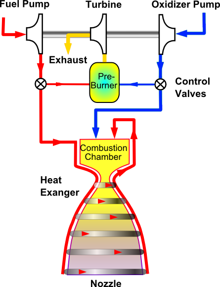
Gas-generator rocket cycle. Some of the fuel and oxidizer is burned separately to power the pumps and then discarded. Most gas-generator engines use the fuel for nozzle cooling.

   For instance, with the relatively low fuel flow possible without the turbopumps would this supply sufficient cooling to the combustion chamber and nozzle?

 There is also the question of how much thrust you can get at this low pressure. Typically for pump-fed engines, the propellant tanks are only held at pressure ranges of about 2 to 3 bar. Necessarily then the pressure within the combustion chamber would have to be even lower than this. You would then have the problem that the pressure in the combustion chamber would be only slightly higher than the surrounding air pressure at sea level, making it difficult to get net thrust. If it does work, likely you would need to use more than one Merlin for the landing, possibly all of them,

 Another possibility for getting lower thrust would be to emulate the "thrust augmented nozzle" proposal of Aerojet. This works in analogous fashion to an afterburner for fighter jets. It would inject additional propellant into the nozzle to get higher thrust, so you have actual combustion going on both in the combustion chamber and in the nozzle.

 A modification to this idea would be to just inject the fuel, not the oxidizer, into the nozzle. Since this is to be used just for landing you would have sufficient air for combustion. The advantage of this is that you would save on the total propellant required for the landing since the oxidizer would not be used.


  Bob Clark

UPDATE, July 8, 2015:

 If the Merlin can not be made to be pressure-fed, SpaceX does have a pressure-fed engine, the Kestrel. It was used on the upper stage of the Falcon 1. It had an approx. 3,000 kilogram-force vacuum thrust. Being an upper stage engine it would have reduced thrust at sea level.

 Moreover, it was designed for the 200 psi tanks of the Falcon 1 upper stage. The Falcon 9 tanks, for the pump-fed Merlins, would be at lower pressure, perhaps in the 50 psi to 100 psi range. This would mean the thrust would be even further reduced.

 For a ca. 15,000 kg dry mass F9 first stage you might need 8 to 10 of the Kestrel's with their reduced sea level thrust. The mass penalty would not be severe since they only weighed 52 kg. And they would weigh even less than this in this application since you would greatly reduce the nozzle size to operate at sea level. There is also the fact that for a first stage, extra mass added to the stage only subtracts a fraction of this added mass from the orbital payload capacity.

Ariane 5 Core plus 4 Ariane 4 side-boosters as a manned launcher, page 2: use as another ISS supply vehicle.

Copyright 2015 Robert Clark


  In the blog post "Ariane 5 Core plus 4 Ariane 4 side-boosters as a manned launcher", I suggested such a configuration would give a quicker, cheaper implementation of the Ariane 6 that would have the advantage that it could also be used as a manned launcher. 

Ariane 5 Core plus Ariane 4 side boosters added

 A recent news report gives this even greater importance, the fact that France wants to sell its stake in Arianespace to Airbus Safran:

French Divestment Will Put Arianespace in Airbus Safran’s Hands.
by Peter B. de Selding — June 10, 2015
http://spacenews.com/french-divestment-will-put-arianespace-in-airbus-safrans-hands/

 This is good news for the commercial space approach to lowering launch costs. For instance, the use of solid rocket side boosters on the Ariane 6 helps to subsidize the French military's use of solid rocket missiles. Without the French government owning a part of the company, you are freer to choose the most cost-effective approach instead.

GEO satellite launcher.
 The calculation for this configuration without an upper stage was for 15 metric tons(mT) to LEO. Much of the satellite launch market however is to geosynchronous orbit. Using an existing upper stage for this version would eliminate another development cost for the current version of the Ariane 6 which envisions a new large upper stage using the new Vinci engine.

 For this configuration use instead the already developed Ariane H10-3 upper stage. This has a 1,570 kg dry mass, 10,470 kg propellant mass, 62.7 kN vacuum thrust and 446 s vacuum Isp. Plug these numbers in for the upper stage into Schilling's launch performance calculator with the same numbers for the Ariane 5 core and Ariane 4 liquid-fueled side-boosters as used in the "Ariane 5 Core plus 4 Ariane 4 side-boosters as a manned launcher" post.

 For GEO satellites the launchers actually send the satellites to geosynchronous transfer orbit (GTO) which is a highly elliptical orbit that reaches from LEO to GEO, with the satellites onboard propellant and engines providing the final kick to a circular orbit at GEO. For the GTO orbit, enter in Schillings calculator the default perigee of 185 km, 35,000 km for the apogee, and an inclination of 5.2 degrees to match the latitude of the Ariane launch site. Then the calculator gives the results:


Mission Performance:
Launch Vehicle:  User-Defined Launch Vehicle
Launch Site:  Guiana Space Center (Kourou)
Destination Orbit:  35000 x 185 km, 5 deg
Estimated Payload:  7948 kg
95% Confidence Interval:  6380 - 9952 kg

"Payload" refers to complete payload system weight, including any necessary payload attachment fittings or multiple payload adapters
This is an estimate based on the best publicly-available engineering and performance data, and should not be used for detailed mission planning. Operational constraints may reduce performance or preclude this mission.


Lowered development costs reduces launch pricing. 
 Replacing the solids with the liquid-fueled boosters that had already been used on the Ariane 4 would eliminate the development costs of having to develop the new solids now planned for the Ariane 6. Since the need to recoup development costs amounts to a significant proportion of the launch price of rockets, the minimal additional development costs would make it much easier for this version of the Ariane 6 to meets its low launch cost goals. And in addition to the much lowered development costs, the minimal additional development would lead to a rapid route to its deployment.

 Also, ESA is considering some versions of the reusability in returning the engine compartment of the core stage. However, by using liquid side boosters you can make the side boosters reusable as well by doing a vertical landing on those.

 Inexplicably, in ESA trade analyses of liquid-fueled versions for the Ariane 6 versus solid booster versions, no consideration was given to the major advantage of liquid fueled versions of providing Europe with an independent manned launch capability. Note this all liquid implementation would give a manned vehicle using four liquid-fueled boosters attached to the core stage, as both the
Russians and the Chinese have done to produce their manned launchers. And because of the rapid development time due to the minimal new development needed, Europe could probably field this manned launcher by the time the Americans field theirs, expected in 2017.

Use as an ISS supply vehicle.
 Last months failure of the Falcon 9 launch to resupply the ISS reveals another reason such fast development time is important. All three of the current ISS cargo launchers have experienced recent launch failures. Then another launcher to serve as a cargo supply vehicle would be useful. Because it would have a short development time and low development cost, this version could serve as valid alternative to the other launchers. Then this opens up another revenue source for this all-liquid version of the Ariane 6.

 Moreover, the Cygnus capsule, being European, could also be used as a low cost cargo capsule, rather than the expensive ATV.


     Bob Clark

Friday, May 29, 2015

A Vertical Landing SSTO - a "Space Shuttle" NASA Missed.

Copyright 2015 Robert Clark


Saturn V's S-II second stage as an SSTO.
The S-II stage during stacking operations of Apollo 6 in the VAB
  
The Saturn V launcher of the Apollo program was remarkable in the lightweight features of its upper stages, the S-II and the S-IVB. This page gives a list of the fueled weights and empty weights of the Saturn V stages:

Ground Ignition Weights

  The mass efficiency of the upper stages led to some proposals to use them together as an independent launcher, the Saturn II:


 However, when this Saturn II was proposed there were not high performance hydrolox engines that could operate at sea level. Therefore it was designed to use the upper stage engine already used on the Saturn V upper stages, the J-2. Since this was not designed to operate at sea level though, this limited the performance of the rocket.

 But in the late 70's when the space shuttle was being designed and built the high performance Space Shuttle Main Engine , the RS-25, was developed. Interestingly, if SSME's were used on the S-II stage you would get a fully reusable rocket as an SSTO that would have comparable payload to orbit as the space shuttle, i.e., no solid rocket boosters required.

 The later versions of Apollo had improved weight optimization. We'll use the specifications for Apollo 14. The "Ground Ignition Weights" page gives the Apollo 14 S-II dry weight as 78,120 lbs., 35,510 kg, and gross weight as 1,075,887 lbs., 489,040 kg, for a propellant mass of 997,767 lbs., 453,530 kg. 

 The SSME has a mass of 3,500 kg while the J-2 had a mass of 1,788 kg. We'll replace the 5 J-2's used on the S-II with 3 SSME's. This increases the stage dry mass by 1,560 kg. We'll use Dr. John Schillings Launch Performance Calculator to estimate the payload to LEO. 

 Enter in 37,070 kg for the stage dry mass, with the new SSME's replacing the J-2's. Enter in 453,530 kg for the propellant mass. Enter in the vacuum thrust with the max thrust at the 109% level in kilonewtons as 3*2,280 kN = 6,840 kN. Enter in the vacuum Isp of 452.3 s. Select "No" for the "Restartable Upper Stage" option, otherwise the payload will be reduced. And enter in an inclination of 28.5 degrees to match the latitude of the Cape Canaveral launch site of 28.5 degrees.

 Then the calculator gives the mass to LEO as 27,077 kg:

Mission Performance:
Launch Vehicle:  User-Defined Launch Vehicle
Launch Site:  Cape Canaveral / KSC
Destination Orbit:  185 x 185 km, 28 deg
Estimated Payload:  27077 kg
95% Confidence Interval:  18536 - 37061 kg

"Payload" refers to complete payload system weight, including any necessary payload attachment fittings or multiple payload adapters

Heat Shield and Landing Legs.
  We'll envision this as a VTVL (vertical take-off vertical landing) SSTO. Then we need to add heat shield, and landing legs. For weight of the heat shield, from the Apollo era it was about 15% of the weight of the reentry vehicle. However, SpaceX's Pica-X is about half the weight so about 8%. One scenario would be for the heat shield to be at the top with the stage entering top first and rotating to put the bottom down after reentry as with this proposal by SpaceX for the Falcon 9 upper stage:


 For the landing legs, that is commonly estimated as 3% of the landed weight:


 However, with modern composite materials we can probably get it to be half that. So call it 1.5%. 

Hovering capability for a VTVL vehicle.
 It was always taken as a given that a reusable VTVL rocket should have hovering capability. See for instance this discussion between noted space historian Henry Spencer and Mitchell Burnside Clapp who worked on both the DC-X and X-33 programs:


 Hovering ability and the low thrust capability this requires allows fine control of both the attitude and velocity in 3-dimensions for unexpected winds on landing. If you don't have that then that limits your ability to make small, fast corrections to attitude and velocity. The result will be repeated over-corrections and over-corrections to those over-corrections until time and space run out:

Hovering capability for the reusable Falcon 9.

 As with the Falcon 9 case, even one SSME would have too much thrust to allow this vehicle to hover. As discussed in the "Hovering capability for the reusable Falcon 9" post, you could apply various attachments to one of the engines to reduce the thrust on landing. You would though have to arrange the engines to be a in a straight-line to have a center engine rather than the clustered arrangement used on the Space Shuttle.

RL-10's as Landing Engines.
 Another possibiliuty to allow hovering would be to use multiple small engines for the landing. The RL-10A5 engine used on the DC-X would work. This is a version of the RL-10 with a shortened nozzle to operate at sea level:

RL-10A-5.

 We'll use eight of them at the bottom of the stage arranged around the outer rim. Since the S-II stage had a 10 meter diameter these would still fit underneath the stage whether the three SSME's were arranged in the clustered format as with the Space Shuttle or in a straight-line.

 These will add 8*143 kg = 1,144 kg to the dry mass, but using them also at launch will add 8*64.70 kN = 517.6 kN to the vacuum thrust.

 Calculated Stage Weight for the Reusable Rocket.
  Adding on the 1,144 kg to the dry mass gives 38,214 kg. At 1.5% of the landed weight for the landing legs this would be 0,015*38,214 kg = 573 kg additional weight to the stage. The estimated propellant that needs to be kept on reserve for landing as discussed in the "horizontal vs. vertical landing" link, is about 10% of the landed weight. This would be about 3,879 kg reserve propellant. This plus the landing legs brings the reentry mass to 42,665 kg. The heat shield weighs 8% of this to bring it to 46,079 kg. 

Calculated Payload for the Reusable Rocket.
 We'll enter in now into the Schilling calculator 46,079 kg for the dry mass, subtract off the 3,879 kg kept on reserve from the propellant mass, and add on 517.6 kN onto the vacuum thrust. The result is:

Mission Performance:
Launch Vehicle:  User-Defined Launch Vehicle
Launch Site:  Cape Canaveral / KSC
Destination Orbit:  185 x 185 km, 28 deg
Estimated Payload:  18706 kg
95% Confidence Interval:  10073 - 28808 kg

"Payload" refers to complete payload system weight, including any necessary payload attachment fittings or multiple payload adapters

This is an estimate based on the best publicly-available engineering and performance data, and should not be used for detailed mission planning. Operational constraints may reduce performance or preclude this mission.


 This is less than the shuttle, but we can increase the payload as was done with the shuttle by using aluminum-lithium alloy for the propellant tank. This can shave off 25% from the propellant tank weight.

Payload Increase on Switching to Aluminum-Lithium Tanks.
 The propellant tanks on the S-II weighed 3% of the total stage weight:
SP-4206 Stages to Saturn
7. The Lower Stages: S-IC and S-II
S-II CONFIGURATION
The S-II turned out to be a comparatively advanced stage in terms of the existing state of the art. Although the S-II carried about 426 400 kilograms of liquid oxygen and liquid hydrogen, the tank structure, though supporting the structural mass, accounted for just a shade over three percent of the stage's total fueled weight. A common bulkhead much larger than that in any previous rocket averted the need for an [212] interstage between the oxidizer and fuel tanks; this reduced the total length of the stage by over 3 meters and saved about 4 metric tons of extra weight. In technical terms, the fabrication of the bulkheads called for unusually demanding accuracy in meridian welds that joined the bulkhead gores together. The welding operation joining the curved, 6-meter-long seams together had to be made to specifications allowing less than 0.33 millimeter of a mismatch. Then there was the problem of insulating the big liquid hydrogen tank, filled with thousands of liters of the super-cold propellant. Otherwise, the basic design elements of the S-II seemed conventional enough in that it consisted of eight major structural components and six major systems, all of which reflected the usual kind of basic elements associated with both the S-IC and the S-IVB.28
http://www.apolloproject.com/sp-4206/xch7.htm

  Then the 3% of the S-II gross mass of 489,040 kg would be 14,671 kg for the propellant tank mass. A 25% savings by switching to Al-Li would be 3,667 kg. This would bring the payload to 22,373 kg, about the same as the Space Shuttle.


  Bob Clark


Friday, April 17, 2015

Hovering capability for the reusable Falcon 9.

Copyright 2015 Robert Clark


 We have now two landing attempts by the reusable F9 first stage onto the SpaceX barge. Both were unsuccessful. From the appearance of both failed landings it would appear that the capability to hover could have made both landings successful:


 About this latest test landing, Elon Musk in a Tweet has acknowledged that not being able to hover will result in a high g landing:

__________________________________________________________________________
__________________________________________________________________________


   This is confirmed by the rather high rate of descent apparent in the video, even though, as has been reported, the video is slowed down.

 Another disadvantage of not having hovering capability is apparent in the video. In correcting for mistakes in the angle of tilt, the engine having limited throttle capability will tend to over correct. That is, without hover and its low thrust capability, you can't make fine adjustments to the rocket orientation. Then at low altitude with little time to make corrections to the over-corrections, this can lead to failed landing due to the need for repeated adjustments and readjustments.

 In the blog post "Merlin 1A engine for a hovering Falcon 9 v1.1 first stage" I suggested one possible solution to the hovering question would be by using the lower thrust Merlin 1A engine. However, it would have to be made throttleable for this to work. In further updates to that blog post, I suggested either using the preburner exhaust or using variable size nozzles.

 Indeed all the proposals discussed in the "Altitude compensation attachments for standard rocket engines, and applications" post could also be used to make variable nozzle attachments to the engine nozzles to reduce the thrust when needed to allow hovering. For instance the carbon nanotube "rubber" attachment could be made to restrict the exit area to reduce the thrust and the "internal spike" proposal could be made to flare out to direct some proportion of the thrust laterally outwards rather than downwards to reduce the downwards thrust.

 These would reduce the efficiency of the engines, i.e., the Isp would be decreased for the hovering proportion of the flight. However, the altitude compensation attachments actually increase the payload perhaps as much as 25% for multi-stage rockets so overall the result will still be an improvement of the payload capacity.

 These altitude compensation attachment proposals do need more R & D work however, and SpaceX might want a quicker fix that can be attached quickly to the engines, or likely just the central engine for the landing phase.

 A possibility is suggested by this collapsible vegetable steamer:


 You would make an attachment like this that could flare out or be closed up, except it would have no holes on the sides. The open position would be usual formation used during the flight. The closed up position would be used only during hover to restrict the thrust.

 Another simple attachment might be the exhaust steering vanes used on rockets prior to the advent of engine gimbaling for steering:


      They could be used to direct a portion of the thrust laterally to reduce the downward thrust.


    Bob Clark


 UPDATE, April 21, 2015:

 Someone suggested to me another method to restrict the thrust to allow hovering, the variable nozzles put on some fighter jet engines:


Friday, April 3, 2015

Atmospheric humidity for water generation.

Copyright 2015 Robert Clark

*Suggestions for Water Production for California.*

California is still in the midst of a huge drought:

California’s About to Run Out of Water. We Have to Act Now.
Annie Sneed, Science, 03.23.15 7:00 am
http://www.wired.com/2015/03/californias-run-water-act-now/

 The state has now ordered a mandatory 25% drop in water usage.

 There appear to be however relatively simple methods of providing extra water. One is by deriving water from humidity in the air, the other by distilling the water from the ocean. Both would appear to have relatively low cost solutions.

 First the humidity solution. The amount of water in the form of water vapor is substantial, especially at high humidity. A key fact is air can store more water vapor at higher temperatures. But the point is the areas in California with the highest drought level are the areas with routine high temperatures, such as Los Angeles. So lets calculate the amount of water in air in Los Angeles. This page gives a graph of average relative humidity levels in LA:

Average Weather For Los Angeles, California, USA.
The average daily high (blue) and low (brown) relative humidity with percentile bands (inner bands from 25th to 75th percentile, outer bands from 10th to 90th percentile).
https://weatherspark.com/averages/29963/Los-Angeles-California-United-States

 You see that the relative humidity commonly reaches the 80% range and above, especially during the warmer months. The relative humidity is the percentage of the maximum possible water vapor the air can hold based on that temperature, called the saturated vapor density. This page gives a calculator for the saturated vapor density based on temperature.

Relative Humidity Calculation.
http://hyperphysics.phy-astr.gsu.edu/hbase/kinetic/relhum.html

 For a temperature of 80 degrees F, the saturated vapor density is given as 25.4 gm/m3. And for a relative humidity of 80%, this corresponds to an actual amount of water in the air of 20.3 gm/m3, 0.0203 kg/m3.

 However, in actuality when the temperature is highest such as in the afternoon the humidity is lowest, and when the temperature is lowest such as in the early morning, the humidity is highest. So let's use some more representative temperatures and humidities. This page gives the  Los Angeles weather over a two-week period:

Weather past 2 weeks in Los Angeles, California, U.S.A.
http://www.timeanddate.com/weather/usa/los-angeles/historic

 For the period as of today April 3, 2015, for a time during the day when both the temperature and the humidity are high, say, in the 60's range for both, this results in total amount of water in the air of about 10 gm/m3.

*Residential Solutions.*

I.) Some ceiling fans can move quite large amounts of air at a time resulting in quite large amounts of water vapor inflow at a time, if placed for example in residential windows. For instance some fans on this page at their higher speed settings can move 5,000 cubic feet per minute (CFM) of air while using only 30 watts:

ENERGY STAR Most Efficient 2015 — Ceiling Fans 52 inches and under.
http://www.energystar.gov/index.cfm?c=most_efficient.me_ceiling_fans_under_52_inches

  Lower speeds give better energy efficiency, but at the cost of lowered air flow amounts. We’ll use the high speed numbers since we want large air flow to get high water vapor inflow.

 At this high amount of hot air inflow though we would probably want the fan in a basement or attic since we would also need a window for the hot air, once the water is removed, to exit.

 How much water would need to be produced? An average person uses about 50 gallons per day of water:

City Utilities: Water Tips.
http://www.cityutilities.net/resident/pgms/watertips.htm

 So say a residence for a family of 4 needed 200 gallons of water per day. A gallon is 3.785 liters, so this is 757 liters per day. Water weighs 1 kilo per liter so this is 757 kilos per day. Then how long would it take for a fan blowing in 5,000 cubic feet per minute to bring in this much water(vapor)? At 5,000 cfm this is 5,000/3.283 = 141.7 meters per minute.

 At the the 80 degree F and 80% humidity level, each of these cubic meters of air would contain 0.0203 kg of water vapor. So this would amount to 2.88 kg per minute of water. This would take 262.8 minutes, about 4.4 hours. However, since the humidity actually goes down as the temperature goes up we would need to add up the total amount of humidity during a full 24-hour day. Looking up the representative amounts on the "Weather past 2 weeks in Los Angeles, California, U.S.A." page, we see the totals will still be above 200 gallons per month.
 This amount of power, only 30 watts used for 4.4 hours, is also quite small in energy costs compared to what the county of Los Angeles charges for water.

 An additional question to be resolved however is how can we convert this water vapor to liquid water? Air conditioners are able to do this, by accident, by chilling the air. Air dehumidifiers also commonly work this way. This causes water to condense out like happens for example in cool morning temperatures with morning dew. On our relative humidity calculator page, at 80 degrees F and 80% relative humidity, the dew point is only 73.4 F.  However, both air conditioners and air humidifiers use quite high power levels. We want to minimize additional power used.

 Some possibilities:

1.)If the water produced this way is an adjunct to the water received from the city, then we can use the cool water coming from the city water supply, typically around 50 degree F, to cool this air and get the water to condense out.

2.)It would be nice though, since the calculation showed this air-produced water alone is sufficient to supply the entire household water needs, to find a way that didn’t use the city water supply.

a.)Another type of air dehumidifier uses desiccants to absorb water vapor. The desiccant material is then heated to release the water as liquid and the same desiccant is used over again. However, this material typically is a silica compound and you would not want remnants of this to be left in the water. This also uses additional power for the heating step. If a desiccant could be found that is a type of mineral you would normally see for example in spring water then this might work. You would though need to find a way to get the water to be released as a liquid. Heating as with air dehumidifiers would work. However it may be at the high temperature of southern California would be sufficient so this would happen naturally.

b.) A similar possibility derives from the fact that rain droplets can frequently condense in the air out of water vapor at temperatures higher than they would normally do by having nucleation sites:

Cloud condensation nuclei.
http://en.wikipedia.org/wiki/Cloud_condensation_nuclei

 Then we could add nucleators into the air stream to get the air to condense. These nucleators though again would have to be a non-toxic if ingested. Ideal would again be some type of mineral commonly found in mineral water.

c.)To get the water to condense we could also expand the air flow. Rapidly expanding the air would cause the temperature to drop thereby chilling the water. A problem here though is the air flow is so large it might require an unreasonable size of expansion needed to get the needed temperature drop.

d.)Another possibility would be by increasing the pressure of the air. Just as increasing the pressure increases the temperature at which water makes the transition from liquid to gas, the boiling point, so also the temperature at which it makes the transitions from gas to liquid, the dew point, also increases. This page gives a calculator for how the pressure changes the dew point:

Dew Point Conversion Calculator.
http://www.howelllabs.com/resources/dew-point-conversion-calculator/

 Enter in 73.4 degrees F in the known dew point field for our 80 degree F and 80% relative humidity scenario. Enter in 0 for the “psig” field, which measures how far this is above standard pressure in psi. Then a psig of only 4 gives a dew point of 80.3 F. That is an increase in pressure of less than 30% results in the water condensing out.

 We might be able to generate this amount of extra pressure by circulating the air around in a circle by centrifugal force. A problem though is the size of the air stream coming from a large ceiling fan size diameter might make the circle size needed impractically large. We could constrict the air coming from the fan into a smaller pipe diameter, but by the Bernoulli principle this would reduce the pressure. It still may be possible though that some combination of restricted pipe diameter and circulation diameter size could provide the needed pressure change at a practical size.

 Another possibility for using centrifugal force to effect the compression is by breaking up the airflow into multiple tubes at the microscale. The compression in this scenario is by the fact the acceleration around a circle is a = v2/r, v being the speed, and r the radius of the circulation. However, for our scenario the speed would only be around 3 to 4 mph, resulting in low acceleration and therefore compression for a large size pipe. However, by breaking the airflow up into multiple microtubes we can make the radius r very small giving high acceleration even for low speed.
 Support for the idea this can provide the needed compression comes from the several papers published on MEMs (micromechanical systems) rotors and turbines at the mini and microscales. Running at the hundreds of thousands of RPM's range these can provide pressure ratio's of from 2 to 3, sufficient for our purposes.

 At a slow airflow speed of 3 to 4 mph though these microtubes might need to be only be at the micron scale diameter to get such high RPM's. We might also constrict the pipe diameter first, which by Bernoulli's principle will increase the speed, before we break the air flow up into multiple microtubes (patent pending).

 For either the large pipe or microtube solutions using centrifugal force we could instead of bending the tubes around in a circle, have rifling inside the tube to cause the air to circulate helical fashion within the tube.

 II.) For the single fan bringing in 5,000 cfm it was surprising this could be done at only 30 watt power level. It would be interesting to find out then how large we could make the air inflow in for a single residential house. The ceiling-fan sized fan we used was about 1.5 square meters. For an average size house of a 100 m2 floor plan, this would provide about 66 times as much air flow and therefore water, if it were brought in through the roof. So this one home could provide the water needs for 66 other homes.

 This assumes that power requirements are just for running the fan and you would not need power for instance to do the condensing step. Since the power requirements are about at 1/10th that of the cost of water for Los Angeles, the home owner could sell the water at much reduced rates.

 However, it may be possible to reduce or eliminate the need for power to run the fan by using the wind flowing over the roof. A problem though is by the Venturi effect, the wind blowing horizontally over the roof would have the tendency to draw the air out of the house rather than drawing air in. If a solution could be found to draw the air in rather than out while using the air flow of the wind the costs would then be essentially nothing.

*Water Utility Solution.*

 For the water company using this method to produce extra water it becomes particularly simple. The large ceiling-fan type fans discussed in the residential solution only move air in the range of 3 to 4 miles per hour. But wind speeds commonly are above this speed especially in coastal areas. Then you would not even need to use fans for the water utility solution. You would just collect the air driven by the wind in large tubes for processing. Also, for California communities near the coast, using the ocean to supply the necessary cooling to condense the water vapor becomes especially simple (patent pending).

*Sustainable Water Resources*

  Up to 1 billion people don't have reliable access to clean drinking water:

http://wholeworldwater.org/

 This would provide a simple, low cost means of providing clean water, assuming the condensing step could be done without extra power. If a fan is needed, the low amount of power could be supplied by a wind mill or solar power. However, it may be that the air flow from the wind itself would be sufficient and not even a fan would be needed.
.
*Individual Water Production.*

 For a scenario where one is stranded out in the wild or in a life raft without water, the amount of power needed for the fan is so small that it could probably be generated by hand for a single individual just for enough water to sustain life. And considering the wind speed needed is only in the range of 3 to 4 mph a fan might not be needed at all.

 Also, at least for an 80 F and 80% relativity humidity scenario, the 30% extra pressure needed to allow water to condense could be easily supplied by hand. By the Ideal Gas Law PV = RT, to get a 30% increase in pressure we would need to make less than a 23% decrease in volume, assuming we did the compression slowly so as not to increase the temperature. For instance, a piston in a foot long cylinder would only need to make a 3 inch compression to get the needed pressure.
 The life boat case would also be very simple because the condensing could instead be done by using the cool temperatures of the ocean water.


    Bob Clark

Could Blue Origin develop a lander for Artemis III?

Copyright 2025 Robert Clark SpaceX is coming under increasing criticism for its delay in developing the Starship lunar lander: U.S. Is Losin...