Saturday, December 12, 2015

Hovering capability for the reusable Falcon 9, page 3: hovering ability can increase the payload of a RLV.

Copyright 2015 Robert Clark

 Blue Origin successfully landed their New Shepard rocket after reaching suborbital space:


 Observing the last portion of the video showing the landing, deviations from the vertical are visible but the ability to hover allowed it sufficient time to correct.

 Comparing this to the SpaceX Falcon 9 failed attempts at landing it is apparent the inability to hover for the F9 did not allow it sufficient time to make the needed corrections.

 SpaceX has said they want their next test landing to be on land at the launch site. My opinion, they might succeed on the next test or two but they will always have failures without hovering ability.

Merlins in a pressure-fed mode.
 Achieving hovering is not even difficult. In the blog post "Hovering capability for the reusable Falcon 9, page 2: Merlin engines in a pressure-fed mode?" I suggested giving the Merlin the ability to run in a pressure-fed mode. The question was whether this was technically feasible. I found in fact that this process of giving a turbopump powered engine a pressure-fed mode, called an idle mode, had been successfully tested during the Apollo days on the J-2 upper stage engine.

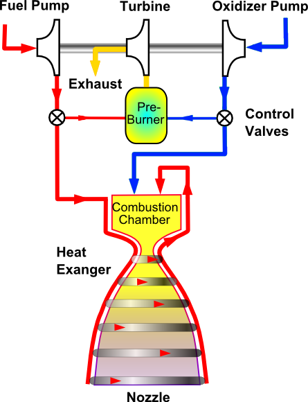
 In giving the J-2 an idle mode though, it was changed from the gas generator cycle that is used by the Merlin 1D to a tap-off cycle:

Rocketdyne J-2.
https://en.wikipedia.org/wiki/Rocketdyne_J-2#J-2S

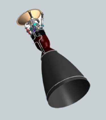
 However, there is an engine that uses the gas generator cycle and has an idle mode, the LE-5 upper stage engine of the Japanese space agency:

Development of the LE-X engine.
https://www.mhi-global.com/company/technology/review/abstracte-48-4-36.html

 In this idle mode though the thrust is significantly less than at full thrust, only 3% in the LE-5 case. If it is a similar low percentage for the Merlin's then all 9 engines would have to be used in this idle mode to allow it to hover on landing.

 The idle mode has an additional advantage since it does not use the turbopumps. It could be used to burn both residual liquid propellant and gases in the tanks. This would mean much less residual fluid would be left in the tank. This then reduces the amount of propellant that needs to be kept on reserve for the landing.

 Elon Musk has also recently said in his Twitter account that the F9 first stage has single-stage-to-orbit (SSTO) capability. For an SSTO the residuals in a first stage can subtract a significant amount from the payload it can deliver to orbit. Then the ability to run in an idle mode with minimal residuals left over can significantly increase the payload for an SSTO. So this would be a further advantage of giving the Merlins an idle mode.

Hovering by use of flexible nozzle extensions.
 In the blog post "Altitude compensation attachments for standard rocket engines, and applications", I discussed another method of achieving hovering capability, attaching nozzle extensions to the bottom of the engines that would allow restriction of the thrust. The flexible high temperature materials already exist in the reentry materials used in NASA's Inflatable Re-entry Vehicle Experiment (IRVE). This has the advantage that the nozzle extension would have to only be applied to the one central engine to reduce its thrust on landing.

 However, the extendable nozzle attachments also have an advantage to the SSTO case. By using an extension that can be retracted at launch and fully extended at high altitude, you can get engines usable at sea level that can reach the high vacuum Isp's usually reserved for upper stage engines. In this way the 311 s vacuum Isp of the Merlin 1D can be raised to the same level of 340 s as the Merlin Vacuum. An increase in the vacuum Isp to this extent can as much as double the payload of a SSTO.

 Note that both of these techniques, idle mode or flexible nozzle extensions, would mean hovering capability can actually increase the payload rather than reduce it.

    Bob Clark

Tuesday, October 27, 2015

Nuclear powered VASIMR and plasma propulsion doable now, Page 3: High efficiency conversion enables zero radiator mass.

Copyright 2015 Robert Clark

Low Radiator Mass at High Efficiency.
 Discussions on various forums have argued the point that actually low conversion efficiency is preferred to save on radiator mass. The idea behind this is that by the Stefan-Boltzmann Law, energy is radiated away according to the fourth power of the temperature. So high thermal energy conversion efficiency resulting in low output temperatures would require larger radiators than with low conversion efficiency with high output temperature. This is explained on this page:

Heat Radiators.
"As an example of the severity of this problem, let us examine the case of a
simple nuclear power plant whose energy conversion efficiency from thermal
to electric is approximately 10 percent. The plant is to generate 100 kW of
useful electricity. The reactor operates at approximately 800 K, and a
radiator with emissivity equal to 0.85 would weigh about 10 kg/m2. The
thermal power to be dissipated from the reactor would be about 1 MW. From
the Stefan Boltzmann Law, the area of the radiator would be about 50 m2 and
the mass approximately 500 kg. This seems quite reasonable.
However, we must assume that the electricity generated by the power plant,
which goes into life support systems and small-scale manufacturing, would
eventually have to be dissipated also, but at a much lower temperature
(around 300 K). Assuming an even better, aluminum radiator of about 5 kg/m2,
with again an emissivity of 0.85, in this case we find that the area of the
low temperature heat rejection component is 256 m2, with a mass approaching
1300 kg."

http://www.projectrho.com/public_html/rocket/basicdesign.php#radiators

 This web site by the way provides a nice collection of the work that has been done on advanced space propulsion systems.

 An additional problem though in regards to low efficiency conversion is that you need higher mass for the reactor and larger amounts of radioactive material that needs to be launched to orbit. For example in the blog post:

"Nuclear powered VASIMR and plasma propulsion doable now, Page 2,"
http://exoscientist.blogspot.com/2015/10/nuclear-powered-vasimr-and-plasma.html ,

I suggested running the reactor at low power to extend the lifetime. In this mode the reactor weighing 2,200 kg would put out 8 megawatts using 200 kg of uranium fuel. If instead of the high conversion efficiency I was aiming for, we selected 10% conversion efficiency, we would need a 10 times larger reactor and 10 times more radioactive fuel. This would put the mass of the reactor at 22,000 kg and the uranium fuel at 2 tons.

 There might be some methods to reduce the heat that needed to be radiated away in the high efficiency scenario. For example Stirling engines can operate even at low temperatures. We could use these to make use of the heat at low temperatures coming from the turbines of  our generator.

 There is also research on lightweighting radiators such as by using carbon-carbon composites:

High Conductivity Carbon-Carbon Heat Pipes for Light Weight Space Power System Radiators.
NASA/TM—2008-215420
http://ntrs.nasa.gov/archive/nasa/casi.ntrs.nasa.gov/20080045532.pdf

 However an interesting possibility exists that we might not need any radiators at all for the high efficiency case

  In the high efficiency case at low output temperature, you can bring the output of the working-fluid down to cryogenic temperatures, as for example for a de Laval nozzle exhausting out to vacuum. If the electric generator equipment is at room temperature, or chilled to decrease resistance and therefore increase power output and specific electric power, then we can have the working-fluid output temperature be lower then the electric generator equipment. So it can used to remove the heat given to the electric generator due to small proportion of thermal not converted to electric power.

 Note this would not obtain for the low efficiency, high output temperature case. If the output is at, say, 800 K to 1,000 K, then by the Second Law of Thermodynamics (Clausius form) we could not use this to cool the generator operating at, say, 300 K or below.

 However, by exhausting down to cryogenic temperatures we could use the cold working-fluid to cool the generator. 

 We need also to cool the turbine. Turbines can be at 90%+ efficiency. The turbine however will be receiving the working fluid at the output temperature. We can though allow the working-fluid to expand further after exiting the turbine to drop to a lower temperature. This then could be used also to cool the turbine.

 An additional factor to provide cooling are the nozzle extensions used for high expansion ratio upper stage engines. For example the RL10-B2 nozzle extensions increase the area ratio to 285-to-1.


 The nozzle extension doubles the weight of the RL10 engine from 150 kg to 300 kg, so weighs 150 kg. The upper part of the nozzle is regeneratively cooled but the carbon-carbon extension is only radiatively cooled. The RL10-B2 engine puts out ca. 250 MW of power measured by its 110 kN thrust and 465.5 s Isp. 

 Because of the low mass of the spacecraft due to the short travel time the power level for the plasma propulsion can be less than 10 MW. Then, with regeneratively cooled upper nozzle section, the nozzle extension to bring the exhaust output down to cryogenic temperatures for this power level might only be 1/25th as large, so only 6 kg(!)

Correction to fuel replacement mass.
 In the comments section to the "Nuclear powered VASIMR and plasma propulsion doable now, Page 2" post, Rok Adamlje noted that my estimate for the fuel canister mass that needed to be replenished was too small. I was taking it to be just the uranium fuel mass when the actual total canister mass may be ten times higher.

 In the section there titled, "Long Life by Multiple Nuclear Fuel Canisters", I calculated the average specific power when using 468 fuel canisters at 200 kg each to last the 39 days of the flight. If we take the fuel canisters instead to be 2,000 kg then we can still get high average specific power by jettisoning the used canisters: 

 The rest of the engine mass, which will be fixed, is a small proportion of the total mass of the fuel canisters so we'll calculate the average specific power based on just the total fuel canister mass. The average specific power will be:

  545 MW       545 MW                  545 MW         545 MW
 ------------ +  --------------- + ... +  -------------  +  -------------
  468*2,000      467*2,000                2*2,000          1*2,000
-------------------------------------------------------------------------
  468


545MW     1               1                    1            1
 --------- (-------- +    ------- + ... +  --------  +  -------)
  2,000       468          467                  2            1
=  ----------------------------------------------------------------------
         468


 The summation in the numerator is the sum of the reciprocals of the natural numbers and is well approximated by the natural log function ln(n). So this will be:

(545,000,000/2,000) *(ln(468)/468) = 3,580 W/kg, still above the 1,000 W/kg level needed for the plasma propulsion.

 Note though the length of time the engine will need to be run is actually less than 39 days because of the small mission size due to the fast travel time. So we'll need fewer replacement fuel canisters and the actual average specific power will be greater.

 Also it could be much of the canister(s) can be reused, primarily replacing just the uranium fuel. This will also increase the average specific power.

      
        Bob Clark

Sunday, October 4, 2015

Nuclear powered VASIMR and plasma propulsion doable now, Page 2.


Copyright 2015 Robert Clark


 In the blog post "Nuclear powered VASIMR and plasma propulsion doable now", I argued that nuclear space reactors already have the capability to do fast transit times to Mars using plasma propulsion systems such as VASIMR or Hall effect thrusters.

Low Power Operation for Long Life.
 However, there was a key fact left out of that analysis: when space nuclear reactors are run at full power they only have limited lifetimes, measured in hours:

Bimodal NTR.
Engine (Thrust Mode)
Thrust per engine 67,000 N
Total Thrust 200,000 N
T/Wengine 3.06
Exhaust Velocity 9,370 m/s
Specific Impulse 955 s
Propellant
Mass Flow 7.24 kg/s
Full Power
Engine Lifetime 4.5 hours
Reactor Power 335 MWthermal
http://www.projectrho.com/public_html/rocket/realdesigns.php#bimodalntr

 This is alright for the applications usually thought of the nuclear rocket engines where they are used only for a few minutes for takeoff and landing.
 But for plasma propulsion as with other types of electric propulsion they achieve high speeds by running them continually for days. Note though that in examples such as the Bimodal nuclear thermal rocket (NTR), they have two modes of operation, a propulsive mode at full power, and an electricity generator mode at greatly reduced power.
 It is in the low power, electricity generator mode that they can run for months to years. Then one idea to deal with the short lifetime at full power is to run the engines at an intermediate power level that will allow them to run for just the few days needed for plasma propulsion.
 We'll use this report to estimate the possible run-times when operated at lower power:

A One-year, Short-Stay Crewed Mars Mission Using Bimodal Nuclear Thermal Electric Propulsion (BNTEP) - A Preliminary Assessment.
http://ntrs.nasa.gov/search.jsp?R=20140009579

 This report is interesting in that it uses the nuclear thermal engines for high thrust maneuvers such as Earth departure and slowdown at Mars arrival, and electric propulsion for the long interplanetary traverse to Mars. I envision as well low thrust electrical propulsion would be best utilized if they spacecraft is sent far outside Earth's deep gravity well by either chemical or nuclear thermal propulsion before the electrical propulsion system is turned on.
 The full power level for the engines used in the report is 545 megawatts thermal for each of the three nuclear engines, at a weight of ca. 2,200 kg each. They would only be run at full power for less than two hours however. Most of the trip the engines would be run in low power mode:

 For the 1-year round trip BNTEP mission, the total operational time for the BNTR engines is 324 megawatt - days (MWD) which includes 1.75 hours of high thrust / high power mode operation totaling 40 MWD and 284 MWD of reduce power EP mode operation. Assuming 1.2 grams of U-235 consumed per MWD, the total U-235 fuel loss in each engine is 389 grams. Since each cermet fuel BNTR has in excess 200 kg, the burn-up is less than 0.2% which is quite acceptable.

A One-year, Short-Stay Crewed Mars Mission..., P. 7.

 Then to get a maximum of 324 megawatt-days while using it only in the long life, low power mode for say a 39 day flight time, that would correspond to a power level of 8.3 megawatts for each engine. At a weight per engine of 2,200 kg, that corresponds to a specific power of 3,800 watts thermal per kilo.

Long Life by Multiple Nuclear Fuel Canisters.
 The above method would be to run the engine just at much reduced power to get the long life. Another method would be to run the engine at full power but just have multiple nuclear fuel canisters that can be used when one gets depleted. The mass of the fuel as given in that passage above from "A One-year, Short-Stay Crewed Mars Mission", page 7 is 200 kg. The run time for the engine at full power is given in that report as 2 hours. Then for a 39 day run time you would need (24/2) * 39 days = 468 fuel canisters, for 468 * 200 kg = 93,600 kg. Plus the 2,200 kg for the engine this would be 95,800 kg for the nuclear power system. Since in this case the engine is always running at full power this would be 545,000,000 W/95,800 kg = 5,700 watts thermal per kilo specific power. You could improve the average specific power perhaps by a factor of 2 by jettisoning the depleted fuel canisters.

Short Flight Time Actually Gives Smaller Mission Size.
 Actually in a follow up post I'll discuss the specific power is actually higher in both these methods because the engines will not have to be run the entire 39 days to get the high delta-v needed for the short flight times. The main reason is you can use a much smaller habitat perhaps only 6 metric tons when the flight time is only about a month compared to the 25 metric tons or higher usually estimated for a 6 to 8 month flight time. I discuss this in the blog post, "Propellant depots for interplanetary flight." This then would translate into a smaller fuel load and shorter burn time.

 In fact, the surprising conclusion you get is the short flight time requiring high delta-v results in a smaller mission size.

Efficiency of Conversion to Electrical Power.
 Remember to get VASIMR or Hall effect thrusters at the 39 day flight time, we only need 1,000 watts per kilo as discussed in "Nuclear powered VASIMR and plasma propulsion doable now". But this has to be electrical power, not the thermal power of the NTR's. To get the conversion of the thermal to electrical power, I suggest turbines modeled on the Space Shuttle SSME's hydrogen turbopumps. These have a remarkable power to weight ratio of 150,000 watts per kilo, and efficiency of 80%:


Space Shuttle Main Engine Orientation.
http://large.stanford.edu/courses/2011/ph240/nguyen1/docs/SSME_PRESENTATION.pdf

 The "turbine efficiency" in the table is the isentropic efficiency. This is the percentage of the ideal efficiency possible with no loss of heat or friction losses. But what we really need to know is the thermal efficiency, the percentage of the thermal energy converted to mechanical power by the turbines.
 Note that the thermal efficiency is limited by the Carnot limit, dependent on the temperature of the thermal source compared to the temperature of the outlet. For the SSME turbopumps the temperature drop is not very large, necessitated by requiring high pressure for injection into the combustion chamber:

 However, by being a space reactor we can have the pressure of the outlet be near vacuum and therefore get a much larger temperature drop. Then the Carnot limit can be above 90% and the 80% isentropic efficiency can put the thermal efficiency above 70%.
 Once you have the conversion to mechanical power the conversion then to electrical can be 95% efficient.
 Ground based power plants including nuclear ones may only get thermal conversion efficiency of ca. 30%. But this is limited by the Carnot limits of the temperatures of thermal source compared to that of the outlet, typically a cold water reservoir.
 For the nuclear powered electrical propulsion, we want to have high efficiency to avoid needing large, and heavy, radiators, to reject the waste heat. If the efficiency were only 30% or below, most of the energy produced is simply thrown away and at great mass penalty.

Can We Improve the Burn Lifetime of Space Nuclear Reactors?
 Space nuclear reactors have full-power lifetimes of just a few hours. This is compared to the fuel burn time of a few years for ground-based nuclear reactors before they need to be refueled. This is due to high temperature and high power level for their size for the space reactors. Indeed the temperature might be 3 times as high at full power for the space reactors compared to the ground ones.
 Most disconcerting is the very small amount of nuclear fuel that actually gets burned because of the short runtime for the space reactors. From that passage in "A One-year, Short-Stay Crewed Mars Mission" cited above, only 0.2% of the nuclear fuel may get burned during the engine lifetime.
 Compare this to the burn-up in ground-based reactors that might be in the range of 6.5%:

The Nuclear Fuel Cycle.
https://web.archive.org/web/20170824054559/http://www.world-nuclear.org/information-library/nuclear-fuel-cycle/introduction/nuclear-fuel-cycle-overview.aspx

 The reason why only a small portion of the nuclear fuel gets burned in any fission reactor is because the fission products after awhile build-up and inhibit the fission process. And the higher the power the reactors are run at for their size, the faster is the build-up of these fission products.
 Then a proposal that might lengthen the lifetime of the space reactors is not to burn the fuel all at once but burn it in layers, outside in. If the layers are thin enough, we should get little blockage from the fission products. Once an outer layer fuel got consumed, we would remove that layer and allow the next layer in to react.
 If we could get most of the fuel to be consumed, then we would need much less radioactive material to be sent to space so nuclear space propulsion would be much less controversial.
 This method might also work for the ground based reactors. If the ground based reactors could use most of the fuel, much less uranium would be needed to operate a reactor and you would have lower operation costs and radioactive waste being produced.


  Bob Clark

Wednesday, September 16, 2015

Applications of transparent solar-powered batteries.

Copyright 2015 Robert Clark

Translucent battery recharges itself with the sun.
Megan Treacy (@mtreacy)
Technology / Clean Technology
September 2, 2015


 Cool tech. This would have a great application to animated or video billboards that could work without an external power supply. In other words you could just paste them up on a wall or on a bus stop and they would work on their own. Here's an example that occurred to me. A recent logo that is supposed to represent climate change is this one:


 This is an animated gif. But the way it is usually presented in magazines and even commonly in online articles is the static jpeg:


 It is much less effective visually that way. That is why I think this would be a great application of a solar powered video billboard. You need the battery component so that it would also work at night. Even better would be if it could be all combined into a single circuity including the LED's providing the display.

 It would also work to combine this transparent solar cell:

Architects rejoice, your all-glass towers could become giant transparent solar cells.
Lloyd Alter (@lloydalter)
Technology / Solar Technology
August 25, 2014

with these transparent batteries:

Transparent lithium-ion batteries make sci-fi gadgets a reality.
By Sebastian Anthony on July 26, 2011 at 6:25 am


  Bob Clark

Thursday, August 27, 2015

Nuclear powered VASIMR and plasma propulsion doable now.

Copyright 2015 Robert Clark


 By now all Mars advocates have heard the argument that VASIMR's 39 days to Mars promise is illusory because the needed space nuclear power sources do not exist at the needed lightweight, ca. 1,000 watts per kilo.

 This led me to propose using concentrated solar power for VASIMR or Hall effect thrusters instead:

Short travel times to Mars now possible through plasma propulsion.
 I was therefore startled to read when looking at the specs of space nuclear engines that the engines themselves actually put out order(plural) of magnitude higher power than this. See for example the specs on the "bimodal" nuclear rocket here:

Bimodal NTR.
Engine (Thrust Mode)
Thrust per engine  67,000 N
Total Thrust  200,000 N
T/Wengine  3.06
Exhaust Velocity  9,370 m/s
Specific Impulse  955 s
Propellant
Mass Flow  7.24 kg/s
Full Power
Engine Lifetime  4.5 hours
Reactor Power  335 MWthermal
http://www.projectrho.com/public_html/rocket/realdesigns.php#id--Bimodal_NTR

 At a thrust of 67,000 N and T/W of 3.06, this means the engine weighs, 21,900 N, or 2,230 kg. So at a 335 MWthermal power this is a 150,000 watts per kg power to weight ratio. And the conversion of this thermal to kinetic energy is over 90% efficient as measured by the engine exhaust velocity.

 This means the problem with getting electrical power out of the space nuclear reactors has nothing to do with the nuclear reactors themselves. The problem is with the conversion to electrical power, specifically, the conversion/generation equipment is too heavy.
 In that vein note then there are electric motors, i.e, electric-to-mechanical conversion, with the necessary lightweight:

Power-to-weight ratio.
2.1.2 Electric motors/Electromotive generators.
 It turns out that electrical-to-mechanical energy conversion and vice versa is very efficient, typically in the 90% range and above. So you would run these electric motors in reverse to generate the electric power. Note then the best in that list is at 10,000 watts per kilo, sufficient for the VASIMR, and other plasma propulsion methods.

 It is important to recognize that the low electrical specific power, i.e., electrical power per weight, for space nuclear reactors is not due to the reactors themselves but due to the electrical conversion equipment. Then the focus is put on improving the electrical power generation weight efficiency. But this has importance beyond just space power systems. For instance the defense department wants lightweight electrical systems to power their UAV's. And aircraft manufacturers are investigating electrically powered aircraft for low-noise and zero-pollution aircraft. For instance LaunchPoint has produced high power density motors for UAV's in the 8200 w/kg range, which they say can be scaled up to large aircraft.

 Another area of research for high specific power motors and generators is operating them at cryogenic temperatures. According to this report 10 times as much power can be put through the windings of a motor at liquid nitrogen temperatures than at room temperature:

HIGH SPECIFIC POWER MOTORS IN LN2 AND LH2.
http://ntrs.nasa.gov/archive/nasa/casi.ntrs.nasa.gov/20070028414.pdf

 Then using the electric motors already getting ca. 10,000 watts/kg, we could conceivably get ca. 100,000 watts/kg by running them at cryogenic temperatures(!) This has great relevance to the space propulsion application since we could use liquid hydrogen or other cryogenics as the fuel that would also serve to keep the electric generator at cryogenic temperatures.


 However, in an upcoming blog post I'll show you don't need to do the conversion to electricity and run a plasma engine. You can get the high speeds from the nuclear engines themselves, with some minor modifications.


  Bob Clark

Thursday, August 13, 2015

Orbital rockets are now easy.

Copyright 2015 Robert Clark


Falcon 1 Upper Stage Based Orbital Launcher.
 In the blog post "On the lasting importance of the SpaceX accomplishment" I suggested that SpaceX's low cost, commercial approach to developing the Falcon 9 will lead to this being emulated by other launch providers and then, eventually, to spaceflight becoming routine. However, ironically, it might turn out their simplest development and one they dispensed with will have the fastest effect towards making orbital access routine.

  It's the Falcon 1 upper stage. Compared to the first stage and certainly compared to the Falcon 9, it's a rather simple stage only using a pressure-fed engine, the Kestrel


Kestrel engine

  Pressure-fed engines and stages are much easier to develop than pump-fed ones. For instance there are the rockets developed by Armadillo AerospaceMasten Space Systems, and Garvey Spacecraft Corporation

 And this was also the case for the Project Morpheus lunar lander stage. In the blog post "The Morpheus lunar lander as a manned lander for the Moon", I discussed the NASA's Project Morpheus emulating a low-cost commercial space approach was able to develop two Morpheus landers for only $14 million. And actually the parts only costs were in the range of $750,000 per lander.

 The construction costs for pressure-fed engines can also be low cost. For instance Project Morpheus was able to produce their engines at a cost of only $60,000:

NASA dreams of future Morpheus project templates.
March 14, 2015 by Chris Bergin
The main engine – which was also tested at the Stennis Space Center – could throttle at a ratio of 4 to 1, ranging between 1,400 and 5,400 pounds thrust. All Morpheus engines were custom designed and built specifically for Morpheus and only cost $60,000 each.

 The specifications for the Falcon 1 upper stage are given here:

Falcon 1.

 It has a 360 kg dry mass and 3,385 kg propellant mass, and a 3,175 kilogram-force vacuum thrust and 327 s vacuum Isp using the Kestrel engine. This is an upper stage engine however with a long nozzle that can't be used at sea level. In the post "Altitude compensation attachments for standard rocket engines, and applications" I described various attachments to be made to existing engines to give them altitude compensation ability. 

 However, since pressure-fed engines are so comparatively low-cost they could be designed from the beginning to have aerospike nozzles. There is for instance the aerospike engine of Garvey Spacecraft. And Firefly Space Systems  will construct an aerospike nozzle by using numerous small engines arranged around a central spike.

 The question though is how much thrust could be developed with the Kestrels at sea level using altitude compensation. I'll estimate from the formula for Isp for a rocket engine:

The ideal exhaust velocity is given by

where k is the specific heat ratio, R* is the universal gas constant (8,314.4621 J/kmol-K in SI units, or 49,720 ft-lb/(slug-mol)-oR in U.S. units), Tc is the combustion temperature, Mis the average molecular weight of the exhaust gases, Pc is the combustion chamber pressure, and Pe is the pressure at the nozzle exit.
http://www.braeunig.us/space/propuls.htm#Isp


 The pressure factor at the end reduces the Isp at sea level. The specific heat ratio k is about 1.24 for kerolox. The Kestrel operates at a chamber pressure of 135 psi. Then the pressure factor is:
sqrt(1-(14.7/135)^(.24/1.24)) =  .591. So the Isp at sea level is 327*.591 = 193 s and the sea level thrust is .591*3,175 = 1,876 kilogram-force. 

 Note for this estimate to be valid you have to have altitude compensation so that the engine has optimal performance at sea level, i.e., you don't have the back-pressure loss that results from non-optimal expansion.

 Because of the 3,745 kg gross mass of the stage though, we need to reduce the propellant load to be loftable by the single Kestrel at the 1,876 kilogram-force sea level thrust. We'll reduce the propellant load by a factor of .45, so to .45*3,385 = 1,520 kg. We want also to maintain the relatively high mass ratio for the stage so we'll reduce the tank size. The tank mass is proportional to the propellant mass. Subtracting off the 52 kg mass of the Kestrel leaves us 308 kg in the stage dry mass. Multiplying this by .45 gives .45*308 = 138.6 kg. Adding on the 52 kg mass of the Kestrel gives a dry mass of 190 kg. 

 Other elements of a rocket stage such as the insulation, wiring, avionics do not scale linearly with propellant mass as does tank mass. However, since for pressure-fed stages the dry mass is so dominated by the tank mass this gives an approximate value of the stage mass when you scale down the stage size. 

 Moreover we can further reduce the dry mass by using composite propellant tanks. Microcosm, Inc. is making small-sized composite tanks that could be used for the purpose. NASA research has shown composite tanks can save 30% off the mass of aluminum-lithium tanks. Since Al-Li tanks save about 25% off the weight of standard aluminum tanks, this means composites can save about 50% off the weight of standard aluminum propellant tanks. 

 To estimate the mass this could save for this application, historically the propellant mass to tank mass ratio for kerolox for standard aluminum tanks is about 100 to 1. Note though this is for pump-fed engines that only need their stages at about 2 bar, about 30 psi. When the tank pressure is increased for pressure-fed engines the tank mass is correspondingly increased. The Falcon 1 upper stage tanks are kept at 200 psi pressure. So for our propellant mass of 1,520 kg, the tank mass assuming standard aluminum might be (1,520 kg/100)*(200 psi/30 psi) = 101 kg. Then a  reduction of 50% in the tank mass would cut 50 kg from the dry mass to bring it to 140 kg. However, we'll calculate here the payload using 190 kg dry mass number, as the dry mass here is approximate since some components of the stage won't actually scale proportionally with the stage size.

Cross-Feed Fueling for Multiple Cores.
 To increase payload we'll use cross-feed fueling. Note that cross-feed fueling is actually a well-understood technology, having been used on the Space Shuttle OMS engines:

Propellant Storage and Distribution.
"The propellant storage and distribution system consists of one fuel tank and one oxidizer tank in each pod. It also contains propellant feed lines, interconnect lines, isolation valves and crossfeed valves.
"The OMS propellant tanks of both pods enable the orbiter to reach a 1,000-foot- per-second velocity change with a 65,000-pound payload in the payload bay. An OMS pod crossfeed line allows the propellants in the pods to be used to operate either OMS engine."

 And it has also been used for decades for jet airliners:

Concorde.
Balancing by Fuel-Pumping.
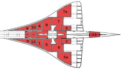
The Concorde Tank-Schematic:

"1 + 2 + 3 + 4 are the Collector-Tanks, feeding the engines directly. Usually they feed there counterpart engines – but they can be cross-switched to feed more and/or other engines at the same time.
5 + 7 and 8 + 6 are the Main-Transfer Tanks, feeding the 4 Collector-Tanks. Initially 5 + 7 are active. If those are empty 6 + 8 take over (or must be activated from the Engineering Panel!).
5a + 7a are Auxiliary-Tanks (to 5 and 7).
9 + 10 are the Trim-Tanks for balancing forward
11 is the Trim-Tank for balancing afterward"

 To emulate rocket cross-feed fueling with the Schilling Launch Performance Calculator, note that during the parallel burn portion of the flight the propellant for the center core engines is coming from the side booster stage(s). This ensures that the center core will have a full propellant load during its solo burn portion of the flight, after the side booster(s) are jettisoned. 

 So the total amount of propellant burned during the parallel burn portion is that of the side booster(s) only. But the Schilling Calculator assumes the amount of propellant burned in the center core during the parallel burn is the same as the amount burned in each side booster. So enter in the Calculator for the booster propellant load a fraction of the actual propellant load of a core equal to the number of side boosters divided by the number of cores. So if you're using 2 cores with one used as a side booster enter in the Calculator booster column 1/2 the amount of the actual core propellant load. And if using 3 cores with 2 used as side boosters, enter in 2/3rds the actual core propellant load in the booster section. This will ensure the Calculator interprets the total propellant burned during the parallel burn portion is that of the actual side booster(s) only.

 But you also want the Calculator to take the amount of propellant burned during the center core's solo burn portion of the flight as that of a full propellant load. Since it is already taking it to have burned the same amount as what the side boosters have burned during the parallel burn portion, add this amount onto the actual propellant load of a core and enter this into a first stage column of the Calculator. For the other specifications for both booster(s) and center core such as Isp, dry mass, and thrust enter in the actual values.

 We'll calculate here the case for using two side booster of same size as the central core. Enter in the Schilling calculator the dry mass of 190 kg for the boosters and the first stage, which is the central core. For the thrust and Isp for the boosters and the first stage, enter in the vacuum Isp of 327 s and vacuum thrust of 31.1 kN in the calculator. However, to emulate cross-field fueling, for the propellant fields enter in (2/3)*1,520 kg = 1,013 kg in the booster section and 1,013 kg + 1,520 kg = 2,533 kg in the first stage section. Choose Cape Canaveral as the launch site and 28.5 degrees as the launch inclination to match the latitude for the launch site. For the "Restartable Upper Stage" select "No", otherwise the payload will be reduced. Then the calculator gives the result:

Mission Performance:
Launch Vehicle:  User-Defined Launch Vehicle
Launch Site:  Cape Canaveral / KSC
Destination Orbit:  185 x 185 km, 28 deg
Estimated Payload:  63 kg
95% Confidence Interval:  19 - 116 kg

"Payload" refers to complete payload system weight, including any necessary payload attachment fittings or multiple payload adapters
This is an estimate based on the best publicly-available engineering and performance data, and should not be used for detailed mission planning. Operational constraints may reduce performance or preclude this mission.


 We could get over 100 kg if we used three side cores. 

Methane for Improved Performance.
 We could also increase the payload using methane instead of kerosene as the fuel. For booster stages, methane has about the same performance as kerosene since the greater density for kerosene makes up for its lower Isp. But for upper stages methane offers better performance since it would give a lighter stage that had to be lofted by the lower stages. So if you wanted to use identical stages for simplicity and cost, methane would be the preferred fuel.

 There is also a key practical reason why methane might be preferred. NASA has developed the methane-fueled engine for the Morpheus rocket stage. With NASA's Technology Transfer program the technical info on the engine would also be shared at least for American companies. Then you would only have to pay the ca. $60,000 construction costs for the engine. 

 Considering that both the Kestrel and Morpheus engines are reusable this already low cost launcher can cut the cost to space considerably. It then could be used for DARPA's proposed reusable launchers discussed here: "NASA Technology Transfer for suborbital and air-launched orbital launchers." In an upcoming blog post I'll also show that using a single one of these cores, it can be used as either the reusable first stage booster, or the air-launched orbital stage for these DARPA programs.

Scale-up to Large Launchers. 
 Note this is a 5,130 gross mass launcher to launch a 63 kg payload. Pressure-fed stages scale up more easily than pump-fed ones since you don't have the complexity of creating a turbopump for the larger size engines. The Mercury spacecraft that carried John Glenn massed 1,300 kg. Using modern materials we could probably make a one-man capsule for 500 kg. Then we would only have to scale up our 3 core launcher by a factor of 8 to launch a one-man capsule to orbit. This would be a 41,000 kg gross mass launcher compared to the 120,000 kg gross mass Atlas rocket that launched John Glenn to space.

  Bob Clark


Tuesday, August 11, 2015

Propellant depots for interplanetary flight.

Copyright 2015 Robert Clark


 In the blog post "The Coming SSTO's: Applications to interplanetary flight" I calculated that IF we have propellant depots at both departure and arrival points then a single Falcon 9 first stage could do ALL the propulsive steps for a flight to Mars, from the LEO departure, to insertion into low Mars orbit, to Mars landing, to Mars liftoff, to departure back towards Earth. 

 The argument there was that this was another key advantage of SSTO's that they would have this capability. But it is important to note that this would be true for all the currently existing medium lift first stages at ca. 20 metric ton (mT) dry mass (without their needing to be SSTO), from the Atlas V, to the Delta IV, to the Soyuz, to the Ariane 5 core, to the Long March 2F, to the H-II. Then all the current spacefaring nations would have the ability to do manned Mars missions with currently existing rockets IF propellant depots are already in place. This is compared to the ca. 1,000 metric ton (mT) total mass estimates for the NASA Mars Design Reference Architectures. 

 Interestingly, when you consider the delta-v requirements for flights to the Moon, Venus, Mercury, and near Earth asteroids then this would also be true for these destinations with propellant depots already in place, perhaps at their Lagrange points. See for instance the Excel spreadsheet describing the Hohmann transfer flights linked on Hop David's page Cosmic Train Schedule. Then propellant depots make possible the long desired goal of Solar System colonization, at least within the inner solar system.

 The Mars flight described in "The Coming SSTO's: Applications to interplanetary flight" using single F9 stage would be flying the usual Hohmann transfer orbit of several months duration. The problems of such space trips in BEO space for several months have been much discussed, from bone and muscle loss, to radiation damage, to the recently discovered eye damage. In fact William Gerstenmaier, head of NASA's human spaceflight division, has said the NASA Mars mission architectures that might take 900 days total round trip are  unworkable:

Yes, NASA really is reconsidering the moon, and here’s why that’s important.
Posted on April 6, 2015 | BY ERIC BERGER
http://blog.mysanantonio.com/newswatch/2015/04/yes-nasa-really-is-reconsidering-the-moon-and-heres-why-thats-important/

 Gerstenmaier suggested, as have many others outside of NASA, that using lunar derived fuel in orbital propellant depots would make Mars missions easier and cheaper. But what has not been discussed is that with propellant depots in orbit the flight times can be cut down from the months long duration to only weeks long. That is, flight times that were thought would need advanced propulsion such as VASIMR plasma or nuclear propulsion could be done by chemical propulsion alone, and in fact using currently existing chemical propulsion stages.

Lightweight Habitat Modules.
 A key fact that needs to be kept in mind is that when the flight times are much shorter then you can use smaller, lighter habitats that need to be transported. This results in a smaller flight vehicle. We can show once again using a single medium-lift first stage we can send a ca. 6 mT habitat to Mars in about 35 days.

 In the post "Budget Moon flights: lightweight crew capsule", I discussed the Phoenix lightweight crew capsule of the University of Maryland aerospace department:

Phoenix: A Low-Cost Commercial Approach to the Crew Exploration Vehicle.

http://rascal.nianet.org/wp-content/uploads/2015/07/2006-RASC-AL-UMD-Tech-Paper.pdf

 This has a pressurized volume of 30 cubic meters with food, air, and water for a crew of 3 for 12 days at a ca. 2 metric ton (mT) dry mass. So putting three together will give enough consumables for the 3 crew for 36 days at a 90 m3 volume and 6 mT mass.

Calculation of flight time to Mars using the Oberth Effect.
 Another advantage of having propellant depots in cis-lunar space such as at L2 and departing from there is the Oberth effect. This is the increase in the rockets delta-v you can get by falling deep into the departure planets gravity well and firing the engines at closest approach. I like this explanation of the effect in Robert Heinlein's book The Rolling Stones:
A gravity-well maneuver involves what appears to be a contradiction in the law of conservation of energy. A ship leaving the Moon or a space station for some distant planet can go faster on less fuel by dropping first toward Earth, then performing her principal acceleration while as close to Earth as possible. To be sure, a ship gains kinetic energy (speed) in falling towards Earth, but one would expect that she would lose exactly the same amount of kinetic energy as she coasted away from Earth.
The trick lies in the fact that the reactive mass or 'fuel' is itself mass and as such has potential energy of position when the ship leaves the Moon. The reactive mass used in accelerating near Earth (that is to say, at the bottom of the gravity well) has lost its energy of position by falling down the gravity well. That energy has to go somewhere, and so it does - into the ship, as kinetic energy. The ship ends up going faster for the same force and duration of thrust than she possibly could by departing directly from the Moon or from a space station. The mathematics of this is somewhat baffling - but it works.
http://www.projectrho.com/public_html/rocket/mission.php#id--Oberth_Effect

  On that www.projectrho.com page is given this formula for calculating the Oberth effect:
To actually calculate the bonus delta V you will get from the Oberth Maneuver:
Vf = sqrt((Δv + sqrt(Vh2 + Vesc2))2 - Vesc2)
Δv = sqrt(Vf2 + Vesc2) - sqrt(Vh2 + Vesc2)
where:
Vf = final velocity (m/s)
Vh = initial velocity before Oberth Maneuver(m/s)
Δv = amount of delta V burn at periapsis (m/s)
Vesc = escape velocity at periapsis (m/s)
 For the propulsion stage we'll use the Ariane 5 "G" core. This has 158 mT propellant load and 12 mT dry mass at 434 s Isp engine. We'll make some small modifications to increase performance. The Ariane 5 core launches from ground so has a intermediate size nozzle to operate at sea level and vacuum. For our use, we're only using it for vacuum so we'll give it a nozzle extension such as on the RL-10B2 Centaur engine to increase the Isp to 462 s. We'll also remove a forward skirt on the core called the "JAVE", from the French "Jupe AVant Equipée", that is used to attach the solids to the Ariane 5. This massed 1,700 kg, bringing the dry mass now down to 10,300 kg.

 Then this can produce an Isp with a 6 mT payload of:

462*9.81ln(1 + 158/(10.3 + 6)) = 10,700 m/s = 10.7 km/s.

  Now use the Oberth effect to calculate the speed after the periapsis burn:

Vf = sqrt((10.7 + 11.1)2 - 11.12) = 18.8 km/s.

 For departure speeds  this high the trajectory is nearly straight-line despite the influence of the Sun. The New Horizons mission gives an example of fast travel times possible with chemical propulsion:

Pluto-Bound Probe Passes Mars’ Orbit.
by Tariq Malik, Staff Writer | April 07, 2006 01:45pm ET
"It's pretty amazing," New Horizons principal investigator Alan Stern told SPACE.com. "It's a straight line across the Solar System. There are hardly any curves because this is so fast." 
New Horizons sped past Mars' orbit some 151 million miles (243 million kilometers) from the Sun at a rate of about 13 miles (21 kilometers) per second. The red planet, however, trailed behind the spacecraft at a distance of about 186 million miles (299 million kilometers), mission managers said, adding that New Horizons was closer to Earth than Mars.
http://www.space.com/2263-pluto-bound-probe-passes-mars-orbit.html

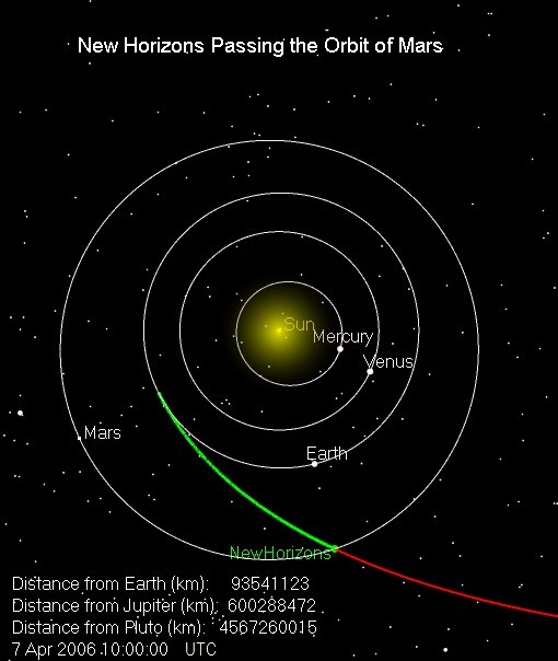
Passing the Orbit of Mars.
New Horizons' trailblazing journey to the solar system's outermost frontier took it past the orbit of Mars at 6 a.m. EDT (1000 UTC) on April 7, 2006 - 78 days after the spacecraft launched.
http://pluto.jhuapl.edu/Mission/Where-is-New-Horizons/Passing-Planets/Passing-Planets-Mars.php

 The distance between Mars and Earth at the time was about 90 million km. The 2018 Mars opposition on the other hand is a particularly close approach at about 58 million km away. At that time for New Horizons to make the trip would have been about 48 days.

 Our flight would be at a faster speed of 18.8 km/s compared to the 12 km/s of New Horizons. Then for the close 2018 opposition, the approximate flight time would be 58,000,000/(18.8*3,600*24) = 35.7 days. This from using a single Ariane 5 core stage, launched dry, fueled at an L2 propellant depot.

Fuel for the propellant depots.
 Because of its proximity the Moon has been often offered for the fuel source for the orbital propellant depots. This would be simpler if the process needs to be supervised by humans. However, some near Earth asteroids have a much smaller delta-v and very much smaller gravity for delivering the fuel to the cislunar system:

Asteroid Retrieval Feasibility Study.
2 April 2012
http://kiss.caltech.edu/study/asteroid/asteroid_final_report.pdf

 Much of the discussion of retrieving asteroids has been about the solar electric ion propulsion used and that perhaps it would cost $2.6 billion to develop. But I was surprised in the report that it also discussed doing it with LH2/LOX chemical propulsion and how little propellant it would use. First it notes that an asteroid such as 2008HU4 at closest approach would require only a 170 m/s (!) delta-v to bring it to lunar orbit. Then in figure 19 on p. 43 is given a comparison between the propellant required for LH2/LO2, N204/MMH, and SEP propulsion for this asteroid at an assumed 1,000 mT mass.

 Surprisingly, for the LH2/LO2 case it is less then 40 mT for a 1,000 mT payload! This is because of course it is only a 170 m/s delta-v. But this means for the 500 mT case that was initially cited for the mission it would be less than 20 mT propellant load, and a LH2/LOX propulsion stage this size is already available in the Centaur. Note also that at an only 170 m/s delta-v to get the Centaur to this asteroid, you would only need to use about 1 mT out of the 20 mT propellant load.

 Since the chemical propulsion would have greater thrust, the mission return time would also be significantly less than the 10 years for the SEP propulsion.

 Planetary Resources, Inc. is launching small telescopes to prospect for asteroids either for mineral resources or for water for propellant. Many asteroids or extinct comets will have large amounts of water ice. Rather than using many rovers to scoop up the surface material for processing, there is an easier approach. Parabolic trough mirrors could be positioned around the four sides of a rectangle on the surface and angled inwards to cut out an upside down triangular prism shaped portion of the asteroid.


Parabolic trough mirror.


Triangular prism.

 Because of the low gravity of the asteroid the water and dust vaporizing will tend to lift the block off the surface.

 Another possibility would be to use microwaves to evaporate the water ice:

Microwaving Water from Moondust.
October 7, 2009.
"We believe we can use microwave heating to cause the water ice in a lunar permafrost layer to sublimate – that is, turn into water vapor. The water vapor can be collected and then condensed into liquid water."
"Best of all, microwave extraction can be done on the spot. And it requires no excavation -- no heavy equipment for drilling into the hard-frozen lunar surface."
He calls his first mining experiment the "Moon in a bottle."
"We filled a bottle with simulated lunar permafrost [fake moondust containing water ice] and heated it in a microwave oven. The microwaves heated the simulant enough to extract water, even though the soil was as cold as it would be on the Moon."
At least 95 percent of the water added to the simulant was extracted (vaporized out of the soil) with 2 minutes of microwaving.
"And we were able to capture 99 percent of the vaporized water in our cold trap," says collaborator Bill Kaukler of the University of Alabama-Huntsville. "It works."
http://science.nasa.gov/science-news/science-at-nasa/2009/07oct_microwave/

 This method of using microwaves was proposed instead of direct heating with sunlight because the lunar regolith does not have very good thermal conductivity and much of the heat would just be re-radiated back. However, the conversion from solar cells to electricity is only about 30% efficient, and the conversion from electricity to microwaves is only about 70% efficient, so this would only be about 21% efficient conversion of the solar energy to the water ice.

 Instead we could cover the area to be illuminated by a dark, non-reflecting material that was reflecting on the reverse side. We would also want it to have good thermal conductivity. Then the heat would be communicated throughout the surface to the regolith/ice below and re-radiated heat from the regolith would be reflected back down into the surface. You could make it be porous so the water vapor could escape.

 In both cases the microwave and the direct sunlight you would cover the area with an enclosing shroud to collect the water vapor that evolved.

 All of these methods could be used on asteroids, the Moon, Mars, and the moons of Mars to collect propellant for orbital propellant depots.

 Another possibility is to use the outgassed volatiles from near Earth comets or cometary fragments:

Dust Whirls, Swirls and Twirls at Rosetta’s Comet.
by BOB KING on MARCH 9, 2015
http://www.universetoday.com/119296/dust-whirls-swirls-and-twirls-at-rosettas-comet/

 The advantage is no landing or solar heating equipment would be required. You could just collect the released H2O, and CO2, CO for hydrocarbon fuel, from orbit. You might want though to enclose the entire comet in a shroud to capture all the released volatiles, as just collecting from orbit would miss most of the released volatiles.

Reentry at Mars.
 These fast travel times using a single medium-lift first stage allow no propellant to slow down. Moreover because of their high travel speed, they will arrive at higher velocity than the normal Hohmann transfer velocity. The Hohmann transfer flight would have a reentry speed of ca. 6 km/s. But with the high transit speeds of 30 day flight duration, the Mars reentry speed might be ca. 20 km/s(!)

 Then new methods would be needed to allow the spacecraft to slow down and land on Mars. In follow-up posts I'll describe various methods of achieving this, from high lift/drag ratio hypersonic airfoils, to ultra lightweight parashields, to magnetoshells, to combusting components of the Martian atmosphere, to expelled propellant forming a cooling gaseous blanket to the reentry heat.


  Bob Clark

Tuesday, July 7, 2015

Hovering capability for the reusable Falcon 9, page 2: Merlin engines in a pressure-fed mode?

Copyright 2015 Robert Clark

 It is understandable that SpaceX wants to use the "hover-slam" approach, which allows no hovering capability, for their vertical landings of the Falcon 9 first stage. This means they would have to make no modifications to their rockets. However, it has always been taken as a given that vertical landing reusable launchers would have hovering capability:

Horizontal vs. vertical landing (Henry Spencer; Mitchell Burnside Clapp).
http://yarchive.net/space/launchers/horizontal_vs_vertical_landing.html

 In the blog post "Hovering capability for the reusable Falcon 9", I suggested various attachments to the Merlin engine nozzles that could serve to give the first stage hovering ability. Here I'll suggest some methods that will provide different means of producing lower thrust from the engines.

 The Merlin's are turbopump fed engines that use moderately high chamber pressures to produce high thrust. But what we want for the landing is actually low thrust. Then rather than using the turbopumps can we use the engines in a pressure-fed mode? The idea will be that during landing the propellant is presented to the engines using the pressurization from the tanks alone, bypassing the turbopumps.

 This requires some care however. If you have additional piping that leads from the tanks directly into the engine combustion chambers bypassing the turbopumps, then you definitely can not have the turbopumps operating at the same time. The reason is the turbopumps will provide combustion at high pressure within the engines and the low pressure coming directly from the tanks would allow hot combustion gases to travel back up these lines into the propellant tanks.

 Indeed, for all engines, pump-fed or pressure-fed, the pressure of the propellants from the piping into the engines is always significantly higher than the pressure within the combustion chamber. This is to ensure the combustion gases do not travel back up into the propellant tanks.

 Another possibility is to just use the usual piping that goes into the turbopumps but insure the turbopumps are turned off during this mode. There are various types of operating cycles used in rocket engines however. Is the gas generator engine cycle used by the Merlins amenable to this mode where the turbopumps are not turning and the propellant is allowed to flow straight through from the tanks into the engine?


Gas-generator rocket cycle. Some of the fuel and oxidizer is burned separately to power the pumps and then discarded. Most gas-generator engines use the fuel for nozzle cooling.

   For instance, with the relatively low fuel flow possible without the turbopumps would this supply sufficient cooling to the combustion chamber and nozzle?

 There is also the question of how much thrust you can get at this low pressure. Typically for pump-fed engines, the propellant tanks are only held at pressure ranges of about 2 to 3 bar. Necessarily then the pressure within the combustion chamber would have to be even lower than this. You would then have the problem that the pressure in the combustion chamber would be only slightly higher than the surrounding air pressure at sea level, making it difficult to get net thrust. If it does work, likely you would need to use more than one Merlin for the landing, possibly all of them,

 Another possibility for getting lower thrust would be to emulate the "thrust augmented nozzle" proposal of Aerojet. This works in analogous fashion to an afterburner for fighter jets. It would inject additional propellant into the nozzle to get higher thrust, so you have actual combustion going on both in the combustion chamber and in the nozzle.

 A modification to this idea would be to just inject the fuel, not the oxidizer, into the nozzle. Since this is to be used just for landing you would have sufficient air for combustion. The advantage of this is that you would save on the total propellant required for the landing since the oxidizer would not be used.


  Bob Clark

UPDATE, July 8, 2015:

 If the Merlin can not be made to be pressure-fed, SpaceX does have a pressure-fed engine, the Kestrel. It was used on the upper stage of the Falcon 1. It had an approx. 3,000 kilogram-force vacuum thrust. Being an upper stage engine it would have reduced thrust at sea level.

 Moreover, it was designed for the 200 psi tanks of the Falcon 1 upper stage. The Falcon 9 tanks, for the pump-fed Merlins, would be at lower pressure, perhaps in the 50 psi to 100 psi range. This would mean the thrust would be even further reduced.

 For a ca. 15,000 kg dry mass F9 first stage you might need 8 to 10 of the Kestrel's with their reduced sea level thrust. The mass penalty would not be severe since they only weighed 52 kg. And they would weigh even less than this in this application since you would greatly reduce the nozzle size to operate at sea level. There is also the fact that for a first stage, extra mass added to the stage only subtracts a fraction of this added mass from the orbital payload capacity.

Currently existing fire equipment could solve the California wildfires within days.

  Copyright 2025 Robert Clark  Several fire fighting equipment manufactures have mobile, high power water pumps:  Such pumps can send water ...