Copyright 2018 Robert Clark
(patents pending)
(I.)Introduction.
Stonehenge has been a mystery for a long time. How did these pre-technology peoples, in the time range of 3,000 to 2,000 BC, raise these huge stones weighing several tons?
Stonehenge has been a mystery for a long time. How did these pre-technology peoples, in the time range of 3,000 to 2,000 BC, raise these huge stones weighing several tons?

A recent theory gaining credence is that they let gravity do the work. The stones actually extend down into the ground. The theory for how they were raised was that they dug a pit under the horizontal stones extending from about a third of the way from one edge. The stones were constructed thicker and so heavier at this edge. Then gravity would cause that end to fall into the pit. This part would then be covered up letting the remaining part be visible above ground.
See for example these videos explaining the theory:
How Stonehenge site was built.
AMAZING VIDEO: Man Lifts 20 Ton Block By Hand.
So rather than the many concerns about building the high altitude towers vertically, instead they would be built horizontally, and we would then follow the Stonehenge builders by allowing gravity to raise them vertically.
For a space tower that might be up to 100 km high however, we would need a deep pit for the one end to fall into, likely kilometers deep. For the purpose, we'll use the deep depths of the ocean. The ocean basins can be in the range of 5 km deep.

We will then put a heavy weight on one end to cause the rest of the tower to rise vertically.
How much will the tower weigh and much will we have to use as a weight on the bottom to raise it? This article gives the formulas for the weight and taper ratio of a tower based on height and materials used.
Alexander Bolonkin
(Submitted on 8 Jan 2007)
https://arxiv.org/abs/physics/0701093
In section 3 are given formulas for the taper of the tower and for the tower mass. The formulas are complicated for the general case where you have to consider the variation of gravity with altitude and centrifugal forces when the tower or elevator may extend thousands of kilometers into space. However, for the shorter case of less than 100 km, it reduces to being exponential in the ratio of the height to the characteristic length.
The characteristic length is the maximal length of a straight, untapered, column of the material that can support its own weight. It is given by Lc = σ/(ρ*g), σ, the compressive strength of the material, ρ is the density and g, the gravitational acceleration at the surface. Usually, you want the tower to be tapered to minimize mass even if it is less than the characteristic length. If it is larger than the characteristic length then it will necessarily have to be tapered..
The formula for the taper is, A = A0*exp[-L/Lc], where A is the area at the top of the tower, A0 is the area of the base, and L the length of the tower. And the formula for the tower mass is, M = M0*(exp[L/Lc] - 1).
Various grades of steel have varying strengths. An especially strong, and expensive, grade is 350 Maraging Steel at a 2,400 MPa compressive strength, and 8,200 kg/m3 density, for a characteristic length of 29.8 km.
There are some composite materials with better strength-to-weight ratios. See for example here:
Mechanical Properties of Carbon Fibre Composite Materials, Fibre / Epoxy resin (120°C Cure)Fibres @ 0° (UD), 0/90° (fabric) to loading axis, Dry, Room Temperature, Vf = 60% (UD), 50% (fabric)
Fibres @ +/-45 Deg. to loading axis, Dry, Room Temperature, Vf = 60% (UD), 50% (fabric)
These tables are for reference / information only and are NOT a guarantee of performance 1 GPa = 1000 MPa = 1000 N/mm² = 145,000 PSI These tables relate to only 2 of the many fibre orientations possible. Most components are made using combinations of the above materials and with the fibre orientations being dictated by the performance requirements of the product. Performance Composites Ltd. can assist with the design of components where appropriate. |
The standard carbon fiber fabric has a compressive strength of 570 MPa at a density of 1.60 g/cc, 1,600 kg/m3, for a characteristic length of 36.3 km. This is the type of fabric that has the fibers aligned in multiple directions.
Unidirectional composites (UD) however have greater strength in the direction of the fibers, and markedly reduced strength outside of that direction. The carbon fiber unidirectional composite (CF UD) has a compressive strength of 1,200 MPa at a density of 1,600 kg/m3, for a characteristic length of 76.5 km, but only in the direction of the fibers.
Another unidirectional composite attains even greater strength using boron fibers. It's compressive strength is listed as 2,800 MPa at a density of 2,000 kg/m3, for a characteristic length of 142.7 km, but again this is only in the direction of the fibers.
The question is whether the unidirectional composites will suffice if the fibers are oriented in the direction of the greatest compressive stress.
Another composite, high-strength structure is the isotruss:

It gains its strength from its unique geometry:

Isotruss Tower
280' tower installed in Spanish Fork, Utah
(II.)Tall Launch Towers.
Geoffrey Landis has calculated that a tower at a 25 km height could make a single stage to orbit(SSTO) financially feasible, increasing the payload by 122%:
High Altitude Launch for a Practical SSTO.
https://ntrs.nasa.gov/archive/nasa/casi.ntrs.nasa.gov/20150012328.pdf
Landis considers using it for a rather large launch vehicle at 2,000 metric tons gross mass. However, I'll consider it for smaller vehicle in the range of 100 metric tons, such as for example the Falcon 9 upper stage, which does have the mass ratio to be SSTO.
We'll calculate the mass of the 25 km tower bearing a 100 ton weight at the top using the various materials. As commonly done for the space tower or space elevator calculations, we'll use a safety factor of 2. That is, in calculating the characteristic length we'll use a compressive strength half of its actual value, giving a characteristic length half of its actual value.
So for the 350 grade maraging steel the exponential term in the mass formula, (exp[L/Lc] - 1), amounts to 4.35. So the mass of the tower would be 4.35 times the 100 ton weight at the top, or 435 tons. Note as a point of comparison, the structural mass of the Eiffel tower at only 300 meters tall is 7,300 metric tons.
For the standard carbon fiber fabric, the exponential term would be 2.96, for a tower mass of 296 tons.
If the unidirectional composites can be used, then the UD carbon fiber gives an exponential term of 0.922, for a tower mass of 92.2 tons, and the UD boron fiber results in a tower mass of 0.42 times 100 tons or 42 tons.
(III.)Launch tracks to orbit.
Some recent proposals for achieving orbit even want to beyond the low costs of reusable SSTO's. They propose creating high altitude tracks on which the space vehicles would be accelerated electromagnetically all the way to orbital velocity. One such proposal is the Lofstrom Launch Loop:

This proposal though would have the tracks be kept aloft dynamically via electrodynamic methods, which would entail the risk of catastrophic failure if the dynamic forces holding it aloft failed. Then it may be preferable to use a static support method.
If the tracks weighed, say, 100 tons between towers supporting the tracks and using the best composite material in the boron UD, the mass of a 100 km tall tower would be 3.06 times 100 tons, or 306 tons.
The towers as 100 km tall pylon supports would be erected using the Stonehenge method one at a time along a line over the oceans. Their mass of, say, 306 tons, would not be an impediment to their being towed out to sea since off-shore drilling platforms weighing hundreds of thousands of tons have been towed out to sea towards their operating locations.
There would be the question of getting the tracks up to the tops of the pylons once they are all erected. The pylons would have a small height at first then gradually having a taller heights until they reach the altitude of the acceleration track, The pylons would then proceed horizontally at common heights. Then each section of the track would be drawn up slowly until they reached their desired positions.
The track sections would need to be able to span the gaps between the pylons though. An automated way of doing it might be this automatic bridge building machine:
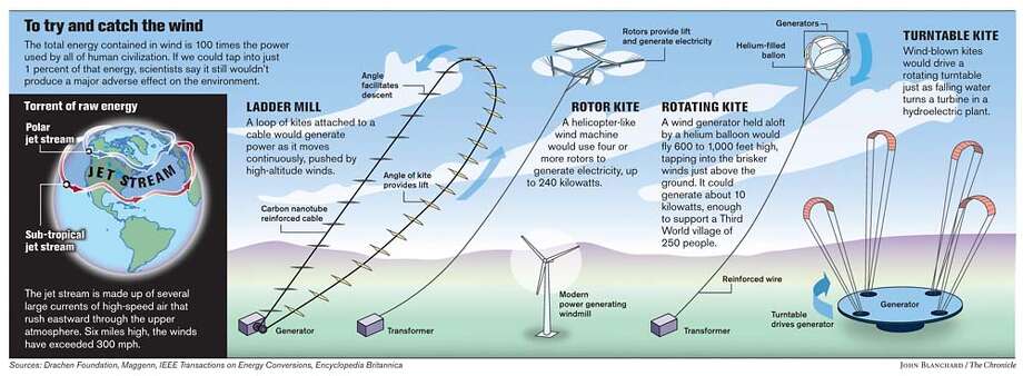
(IV.)Jet stream powered wind mills.
The winds in the jet stream can be in the range of 100 mph, 160 km/hr, 5 to 10 times the common wind speeds at the ground.
The polar jet stream can travel at speeds greater than 100 miles per hour (160 km/h). Here, the fastest winds are coloured red; slower winds are blue.
Since the power of the turbine varies as the cube power of the speed, this means a wind turbine in the jet stream could provide a hundred to a thousand times more power than one on the ground. A single wind turbine might supply 1 gigawatt of power, enough for an entire city of a million people.
This led to several proposals for harnessing the power of the jet stream:
Scientists look high in the sky for power / Jet stream could fill global energy needs, researchers say
Keay Davidson, Chronicle Science Writer Published 4:00 am PDT, Monday, May 7, 2007
 https://www.sfgate.com/science/article/Scientists-look-high-in-the-sky-for-power-Jet-2596175.php
And Bill Gates intends to invest billions in renewable energy such as wind power.
To get to the winds of the jet stream we could use the standard wind mill form of a tall tower with a turbine attached, except we now have the capability to construct those towers to the altitude of the jet stream, ca. 10 km.
As a point of comparison, the Nordex N100/2500 wind turbine generates ca. 2.5 MW using a 100 m wide rotor. The rotor made of carbon composite weighs less than 10 tons. We'll calculate the mass of the tower to 10 km to support that 10 ton weight, using a safety factor of 2 in each case.
For the 350 grade maraging steel, the exponential term in the mass formula is 0.96, so the tower mass to support the 10 ton rotor would be 9.6 tons. For the standard carbon fiber factor, the exponential term would 0.73, for a tower mass of 7.3 tons. And for the boron fiber UD, the exponential term is 0.15, for a tower mass of 1.5 tons.
That 1.5 ton weight using the boron fiber UD is quite remarkable for a tower to reach 10 km high, the altitude jet airliners cruise at. This illuminates how important it is to determine if unidirectional composites can be used for construction of tapered towers.
Bob Clark
The winds in the jet stream can be in the range of 100 mph, 160 km/hr, 5 to 10 times the common wind speeds at the ground.
The polar jet stream can travel at speeds greater than 100 miles per hour (160 km/h). Here, the fastest winds are coloured red; slower winds are blue.
Since the power of the turbine varies as the cube power of the speed, this means a wind turbine in the jet stream could provide a hundred to a thousand times more power than one on the ground. A single wind turbine might supply 1 gigawatt of power, enough for an entire city of a million people.
This led to several proposals for harnessing the power of the jet stream:
Scientists look high in the sky for power / Jet stream could fill global energy needs, researchers say
Keay Davidson, Chronicle Science Writer Published 4:00 am PDT, Monday, May 7, 2007
And Bill Gates intends to invest billions in renewable energy such as wind power.
To get to the winds of the jet stream we could use the standard wind mill form of a tall tower with a turbine attached, except we now have the capability to construct those towers to the altitude of the jet stream, ca. 10 km.
As a point of comparison, the Nordex N100/2500 wind turbine generates ca. 2.5 MW using a 100 m wide rotor. The rotor made of carbon composite weighs less than 10 tons. We'll calculate the mass of the tower to 10 km to support that 10 ton weight, using a safety factor of 2 in each case.
For the 350 grade maraging steel, the exponential term in the mass formula is 0.96, so the tower mass to support the 10 ton rotor would be 9.6 tons. For the standard carbon fiber factor, the exponential term would 0.73, for a tower mass of 7.3 tons. And for the boron fiber UD, the exponential term is 0.15, for a tower mass of 1.5 tons.
That 1.5 ton weight using the boron fiber UD is quite remarkable for a tower to reach 10 km high, the altitude jet airliners cruise at. This illuminates how important it is to determine if unidirectional composites can be used for construction of tapered towers.
Bob Clark


2 comments:
Nice posting.
Hey Friends, Please visit my website and give me suggestion about my website.
www.accrotech-testequipments.com
good thanks for this info
Preventive Maintenance Checklist
Post a Comment